
Milling cutter clamping equipment for manufacturing precision machinery

A technology of precision machinery and clamping equipment, applied in the direction of manufacturing tools, metal processing equipment, metal processing machinery parts, etc., can solve the problems of inconvenient installation, inconspicuous effect of pressing screw, and inconspicuous installation stability of milling cutters. , to achieve the effect of simple disassembly steps

Inactive Publication Date: 2017-08-18
HUANGHE S & T COLLEGE
View PDF7 Cites 17 Cited by
  • Summary
  • Abstract
  • Description
  • Claims
  • Application Information

AI Technical Summary

Problems solved by technology

[0005] To sum up, when the milling cutter in the milling cutter clamping device for precision machinery manufacturing with the patent No. "CN105478874A" is installed, the milling cutter cannot be positioned accurately, which makes it inconvenient to install. In addition, the patent No. "CN205629994U" The pressurization effect of the pressurized screw in a milling cutter clamping device for precision machinery manufacturing is not obvious, and the installation stability of the milling cutter is not obvious, and only one type of milling cutter can be clamped, in order to solve the patent No. For the problems existing in "CN105478874A" and patent No. "CN205629994U", a milling cutter clamping device for precision machinery manufacturing is proposed

Method used


Image

  • Milling cutter clamping equipment for manufacturing precision machinery
  • Milling cutter clamping equipment for manufacturing precision machinery
  • Milling cutter clamping equipment for manufacturing precision machinery

Examples


Embodiment

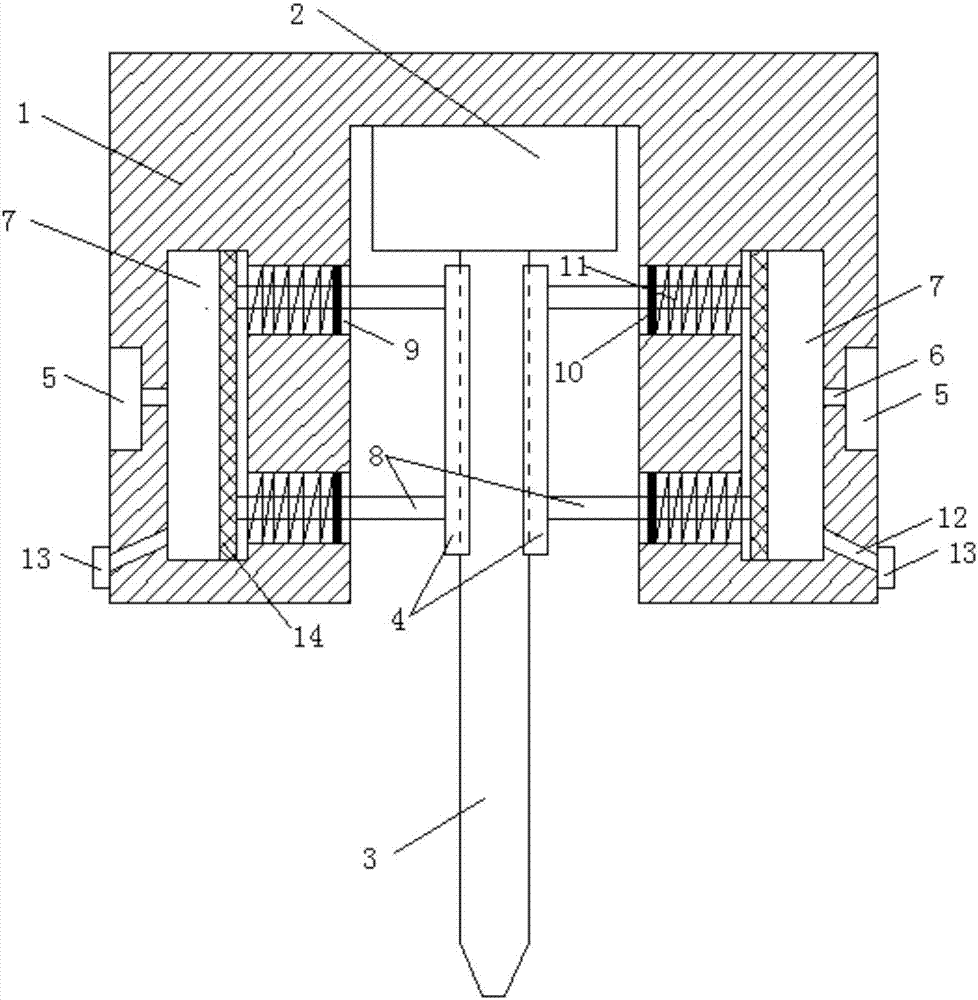
[0032] refer to Figure 1-5 In this embodiment, a milling cutter clamping device for precision machinery manufacturing is proposed, which includes a clamping seat 1 and a milling cutter 3. The clamping seat 1 is a rectangular structure, and a clamp is provided at the center of the bottom of the clamping seat 1. The holding groove, the holding groove is a cylindrical structure, and the central position of the top inner wall of the holding groove is welded with the mounting seat 2, and the central position of the bottom of the mounting seat 2 is provided with a rectangular placement groove 21, and the top of the rectangular placement groove 21 The central position of the inner wall is provided with a five-sided card slot 19, and the interior of the five-sided card slot 19 is fitted with a five-sided card post 18, and the bottom of the five-sided card post 18 is welded with a milling cutter 3, and the top of the milling cutter 3 In contact with the top inner wall of the rectangul...


PUM


Abstract

The invention belongs to the technical field of milling cutter clamping equipment, and particularly relates to milling cutter clamping equipment for manufacturing precision machinery. Aimed at the technical problems that the installation of a milling cutter is not convenient, the enhancement effect of the installation stability of the milling cutter is not obvious, and only one kind of milling cutter can be installed on each clamping seat, now the following scheme is provided, and the milling cutter clamping equipment comprises the clamping seat and the milling cutter. The clamping seat is of a rectangular structure, a clamping groove is formed in the central position of the bottom of the clamping seat, and the clamping groove is of a cylindrical structure; and a mounting seat is welded on the central position of the inner wall of the top of the clamping groove, a rectangular placing groove is formed in the central position of the bottom of the mounting seat, and a pentagonal clamping groove is formed in the central position of the inner wall of the top of the rectangular placing groove. According to the milling cutter clamping equipment for manufacturing the precision machinery, the positioning of the milling cutter is accurate, installation and disassembly of the milling cutter on the milling cutter clamping equipment are convenient, milling cutters with different diameters can be installed in the mounting seat on the inner wall of the top of the clamping groove, and in addition, the installation stability of the milling cutter is also enhanced greatly.

Description

technical field [0001] The invention relates to the technical field of milling cutter clamping equipment, in particular to a milling cutter clamping equipment for precision machinery manufacturing. Background technique [0002] A milling cutter is a rotating tool with one or more teeth for milling operations. When working, each knife tooth cuts off the allowance of the workpiece intermittently in turn. Milling cutters are mainly used for machining planes, steps, grooves, forming surfaces and cutting off workpieces on milling machines. It plays an important role in the processing of mechanical equipment. Milling cutter clamping equipment is usually used in the installation of milling cutter equipment. The commonly used milling cutter clamping equipment has a small clamping force, resulting in poor stability and low safety, which cannot meet the needs of use. [0003] In order to solve the problem that the clamping force of the milling cutter clamping device is small, resul...

Claims


Application Information

Patent Timeline
IPC IPC(8): B23Q3/12
CPCB23Q3/12
Inventor 刘德波杜林豪齐鹏翔齐德安齐俊平
Owner HUANGHE S & T COLLEGE
Learn More