Water bed structure of composite cutting machine

A cutting machine and water bed technology, applied in the direction of manufacturing tools and other manufacturing equipment/tools, etc., can solve the problems of low processing efficiency of water bed structures, achieve reliable processing, improve processing efficiency, and facilitate slag removal

Active Publication Date: 2018-11-06
ZHEJIANG SHENGDA STEEL TOWER
View PDF8 Cites 2 Cited by
  • Summary
  • Abstract
  • Description
  • Claims
  • Application Information

AI Technical Summary

Problems solved by technology

Solve the problem of low processing efficiency of the existing water bed structure

Method used


Image

  • Water bed structure of composite cutting machine
  • Water bed structure of composite cutting machine

Examples


Embodiment Construction

[0025] Below in conjunction with each accompanying drawing, the present invention is described in detail.

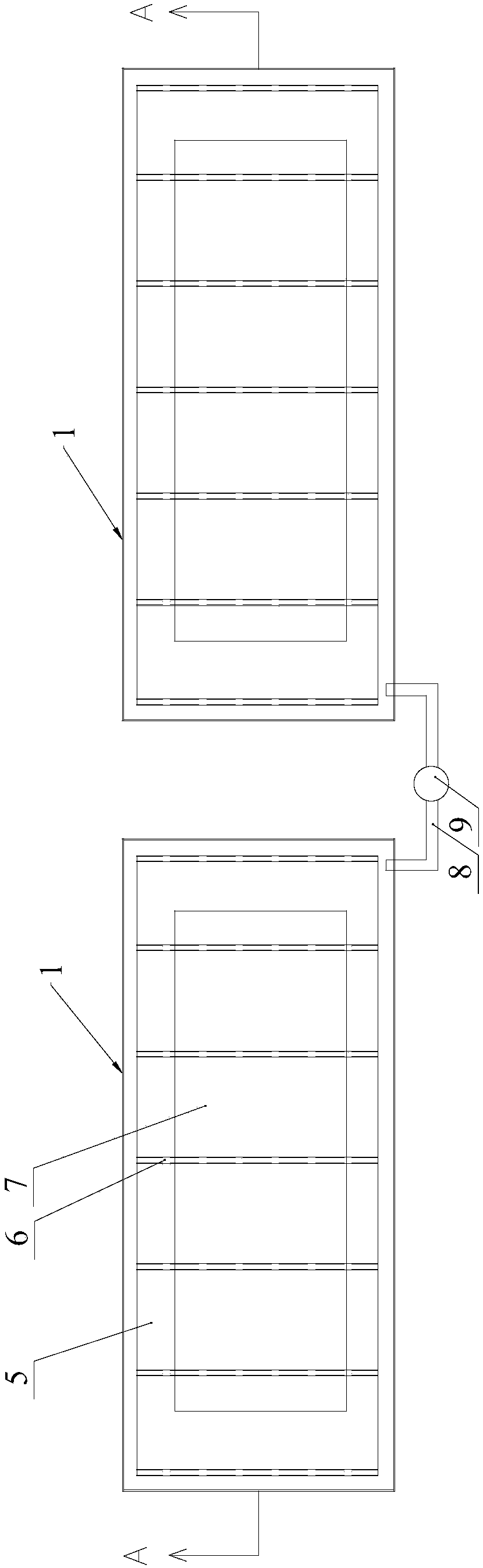
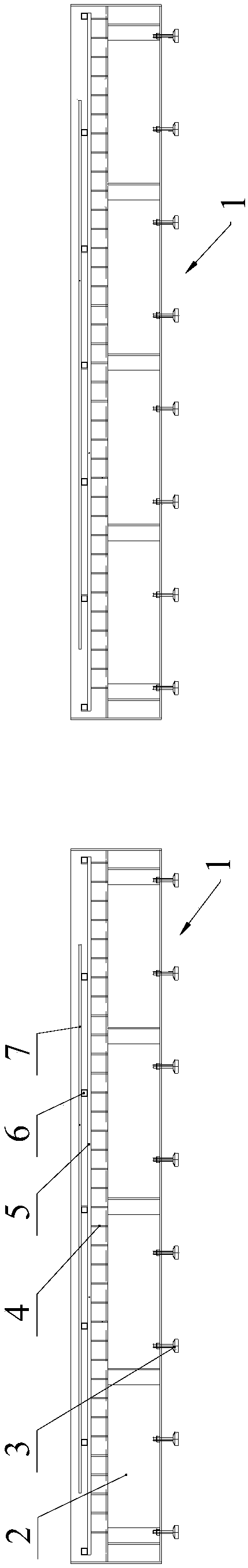
[0026] Such as figure 1 and 2 As shown, a water bed structure of a compound cutting machine includes at least two water bed bodies 1 arranged side by side. The flat plate 5 on the top has a gap between the flat plate 5 and the water storage tank 2, and several support bars 6 are arranged on the plate 5, and the support bars 6 are used to support the plate 7 to be processed; A water pipe 8 of a water storage tank 2, and a water delivery pump 9 is installed on the water pipe 8.

[0027] By arranging a plurality of water bed bodies 1, when the composite cutting machine processes the plate 7 to be processed on one of the water bed bodies 1, other water bed bodies 1 can carry out material handling and slag cleaning work, and the structure of the multiple water bed bodies 1 can Greatly improve processing efficiency. There is a water pipe 8 connecting two water storage tank...


PUM


Abstract

The invention discloses a waterbed structure for a compound cutting machine. The waterbed structure comprises at least two waterbed bodies arranged side by side, wherein each waterbed body comprises a water storage tank, a fence arranged in the water storage tank and a flat plate arranged at the top of the fence, and a gap exists between the flat plate and the water storage tank; a plurality of support strips are arranged on the flat plate and are used for supporting a plate to be machined; a water pipe for communicating the two water storage tanks is arranged between the adjacent two waterbed bodies, and a water-delivery pump is arranged on the water pipe. As a plurality of waterbed bodies are arranged, when the compound cutting machine machines the plate to be machined on one waterbed body, other waterbed bodies can carry materials and remove slag. The structure with multiple waterbed bodies can greatly improve the machining efficiency. The water pipe for communicating the two water storage tanks is arranged between the adjacent two waterbed bodies and can pump water in one water storage tank into the other waterbed body, and therefore the waterbed body with delivered water can reach the machining liquid level height.

Description

technical field [0001] The invention relates to a compound cutting machine, in particular to a water bed structure of the compound cutting machine. Background technique [0002] The compound cutting machine can realize the work of gas cutting, stamping and drilling. The water bed of the existing compound cutting machine is a whole water bed. Dry, and then lift the fence to clear the slag, which takes a long time and the steps are cumbersome, and the compound cutting machine must stop working during the slag cleaning, which greatly reduces the processing efficiency. Contents of the invention [0003] Aiming at the above problems, the present invention proposes a water bed structure of a composite cutting machine. The problem of low processing efficiency of the existing water bed structure is solved. [0004] The technical scheme that the present invention takes is as follows: [0005] A water bed structure of a composite cutting machine, comprising at least two water bed...

Claims


Application Information

Patent Timeline
Patent Type & Authority Patents(China)
IPC IPC(8): B23P23/04
CPCB23P23/04
Inventor 陈卫波蔡威斌黄元勋林捷朱琳张斌张俊
Owner ZHEJIANG SHENGDA STEEL TOWER
Why Eureka
Try Eureka