
A high-efficiency dust removal device

A dust removal device and high-efficiency technology, applied in cleaning methods and tools, cleaning methods using tools, chemical instruments and methods, etc., can solve problems such as low efficiency, time-consuming and labor-intensive, and inability to adapt to existing needs, so as to improve work efficiency, The effect of improving the speed of disassembly and assembly

Active Publication Date: 2018-06-19
江苏乾云环保工程有限公司
View PDF5 Cites 0 Cited by
  • Summary
  • Abstract
  • Description
  • Claims
  • Application Information

AI Technical Summary

Problems solved by technology

[0002] The circuit boards, workpieces and other products produced on the industrial assembly line are often contaminated with some oil, dust and other dirt. Therefore, they need to be cleaned and dedusted before packaging the products. The traditional cleaning method uses a hand-held brush to clean the surface of the product. Sweeping dust is inefficient, time-consuming and labor-intensive, and the automatic dust removal equipment can only fix a certain specification of dust removal brush, and the dust removal brush cannot be replaced according to the actual size of the product, which cannot meet the existing needs

Method used


Image

  • A high-efficiency dust removal device
  • A high-efficiency dust removal device
  • A high-efficiency dust removal device

Examples


Embodiment Construction

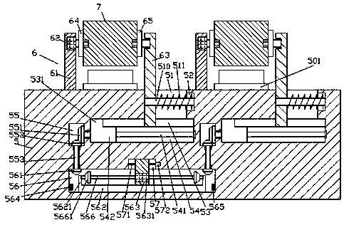
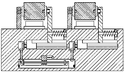
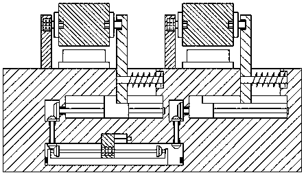
[0026] Such as Figure 1-Figure 8 As shown, a high-efficiency dust removal device of the present invention includes a body 5 and a dust removal structure 6 arranged on the top of the body 5 and correspondingly arranged on the left and right sides. Each of the dust removal structures 6 includes a support column 61 arranged on the left side, a The sliding column 63 on the right side and the dust removal brush 7 arranged between the supporting column 61 and the sliding column 63, the left and right sides of the body 5 are correspondingly provided with guide chambers 54 extending from the left to the right. The tops of each of the guide chambers 54 are provided with grooves 53 extended along the left and right sides of the top of the guide chamber 54, and the tops of the extended sections on the right side of each of the grooves 53 are provided with guide grooves 51. A first sliding block 542 is slidably connected in the guide cavity 54 , and a convex block 531 protruding into the...


PUM


Abstract

The invention discloses a high-efficiency dust collection device. The high-efficiency dust collection device comprises a machine body and dust collection structures arranged on the top of the machine body in a left-right corresponding manner. Each dust collection structure comprises a supporting column arranged on the left side, a sliding column arranged on the right side and a dust collection brush arranged between the supporting column and the sliding column. Moving guiding cavities which are formed in a left-right extending manner are formed in the machine body in a left-right corresponding manner. The top of each moving guiding cavity is provided with groove channels in a through manner, wherein the groove channels extend along the left side and the right side of the top of the moving guiding cavity. The top of the right extending segment of each groove channel is provided with a moving guiding groove in a through manner. Each moving guiding cavity is internally provided with a first sliding block in a sliding fit manner. The left side of the top of each first sliding block is provided with a T-shaped block extending into the corresponding groove channel. Each first sliding block is internally connected with a first screw rod in a thread fit manner, wherein the first screw rod extends left and right. The part, on the left side of each moving guiding cavity, of the machine body is internally provided with a converting cavity. The high-efficiency dust collection device is simple in structure and can efficiently collect dust on workpiece surfaces, equipment investment is reduced, and the manufacturing cost and the maintaining cost are reduced.

Description

technical field [0001] The invention relates to the technical field of dust removal, and relates to a high-efficiency dust removal device. Background technique [0002] The circuit boards, workpieces and other products produced on the industrial assembly line are often contaminated with some oil, dust and other dirt. Therefore, they need to be cleaned and dedusted before packaging the products. The traditional cleaning method uses a hand-held brush to clean the surface of the product. Dust sweeping is inefficient, time-consuming and labor-intensive, and the automatic dust removal equipment can only fix a certain specification of dust removal brushes, and the dust removal brushes cannot be replaced according to the actual size of the product, which cannot meet the existing needs. Contents of the invention [0003] The technical problem to be solved by the present invention is to provide a high-efficiency dust removal device, which can solve the above-mentioned problems in t...

Claims


Application Information

Patent Timeline
Patent Type & Authority Patents(China)
IPC IPC(8): B08B1/04B08B13/00
CPCB08B1/002B08B1/04B08B13/00
Inventor 史乾徐香云徐卫中
Owner 江苏乾云环保工程有限公司
Learn More