Novel dust remover

A dust collector and a new type of technology, applied in the direction of vacuum cleaners, cleaning equipment, household appliances, etc., can solve the problems of cumbersome operation, unsuitable for popularization, time-consuming and laborious dust collectors, etc., and achieve the effect of simple device structure.

Active Publication Date: 2017-08-18
NANTONG LIYUANHENG MACHINERY
View PDF9 Cites 2 Cited by
  • Summary
  • Abstract
  • Description
  • Claims
  • Application Information

AI Technical Summary

Problems solved by technology

[0002] The dust collector is a dust removal tool that is often used in modern furniture life. It is simple, fast, and has a good dust removal effect, so it is widely used. However, the traditional dust collector setting mode is relatively simple. When the dust inside the dust collector is full, it needs to be passed. Manually take out the liner loaded with dust and pour out the garbage. This method is not only time-consuming and labor-intensive, but also the dust collector is easily damaged due to the influence of the force applied by the manual operation. There are also many existing ones that can automatically A dust collector that sends dust backwards, but its use cost is high and the operation is cumbersome, so it is not suitable for popularization

Method used


Image

  • Novel dust remover
  • Novel dust remover
  • Novel dust remover

Examples


Embodiment Construction

[0022] All features disclosed in this specification, or steps in all methods or processes disclosed, may be combined in any manner, except for mutually exclusive features and / or steps.

[0023] Any feature disclosed in this specification (including any appended claims, abstract and drawings), unless expressly stated otherwise, may be replaced by alternative features which are equivalent or serve a similar purpose. That is, unless expressly stated otherwise, each feature is one example only of a series of equivalent or similar features.

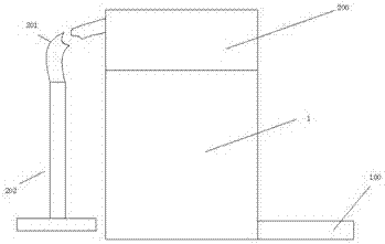
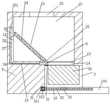
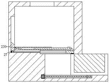
[0024] Such as Figure 1-3 As shown, a new dust remover of the present invention includes a loading part 1 and a dust removal part 200 arranged on the top of the loading part 1. The left side of the dust removal part 200 is connected with a dust suction pipe 201, and the dust suction The end of the tube 201 is fixed with a suction head 202, and the loading part 1 is provided with a loading chamber 10 with the port facing upward and a push-pul...


PUM


Abstract

The invention provides a novel dust remover. The novel dust remover comprises a loading part and a dust removal part arranged on the top of the loading part. A dust suction pipe is arranged on the left side of the dust removal part in a communicated mode. A dust suction head is fixedly arranged at the tail end of the dust suction pipe. A loading cavity with an upward end opening and a push-and-pull groove located below the loading cavity and provided with a rightward end opening are formed in the loading part. A discharge opening is formed between the loading cavity and the push-and-pull groove. A push-and-pull part is installed in the push-and-pull groove in a sliding mode, a loading groove with an upward end opening is formed in the push-and-pull part, a bottom plate stretching rightwards is arranged at the right end of the bottom wall of the push-and-pull groove, a first sliding groove with an upward end opening is formed in the bottom wall of the push-and-pull groove and in the bottom plate, a first sliding block is installed in the first sliding groove in a sliding mode, a screw rod is installed in the first sliding block in a spiracle fit mode, the right end of the screw rod is rotationally installed in the right end wall of the first sliding groove, the left end of the screw rod is connected with an actuator fixedly installed in the left end wall of the first sliding groove, a guide groove stretching left and right is formed in the front end wall and the rear end wall of the discharge opening, and a sliding plate stretching front and back is installed in the guide groove in a sliding mode.

Description

technical field [0001] The invention relates to the technical field of dust collectors, in particular to a novel dust collector. Background technique [0002] The dust collector is a dust removal tool that is often used in modern furniture life. It is simple, fast, and has a good dust removal effect, so it is widely used. However, the traditional dust collector setting mode is relatively simple. When the dust inside the dust collector is full, it needs to be passed. Manually take out the liner loaded with dust and pour out the garbage. This method is not only time-consuming and labor-intensive, but also the dust collector is easily damaged due to the influence of the force applied by the manual operation. There are also many existing ones that can automatically A dust collector that sends dust backwards, but its use cost is high and the operation is cumbersome, so it is not suitable for popularization. Contents of the invention [0003] The object of the present invention...

Claims


Application Information

Patent Timeline
IPC IPC(8): A47L5/36A47L9/00
CPCA47L5/36A47L9/00
Inventor 陈剑波
Owner NANTONG LIYUANHENG MACHINERY
Why Eureka
Try Eureka