
Injection mold with deep-thread bottle cap

An injection mold and deep thread technology, which is applied in the field of injection molds for deep thread bottle caps, can solve the problem that the bottle cap is difficult to come out

Active Publication Date: 2017-08-15
张家港市天江精密模具制造有限公司
View PDF8 Cites 2 Cited by
  • Summary
  • Abstract
  • Description
  • Claims
  • Application Information

AI Technical Summary

Problems solved by technology

[0002] Some injection molds for threaded bottle caps push the bottle cap through the spring in the mold after the bottle cap is injection molded, so that the bottle cap is unscrewed from the mandrel under the action of the spring force, but the injection mold with this structure is used for screw thread When forming a deep cap, it will be difficult to remove the cap

Method used


Image

  • Injection mold with deep-thread bottle cap
  • Injection mold with deep-thread bottle cap
  • Injection mold with deep-thread bottle cap

Examples


Embodiment Construction

[0023] Specific embodiments of the present invention will be described in detail below in conjunction with the accompanying drawings.

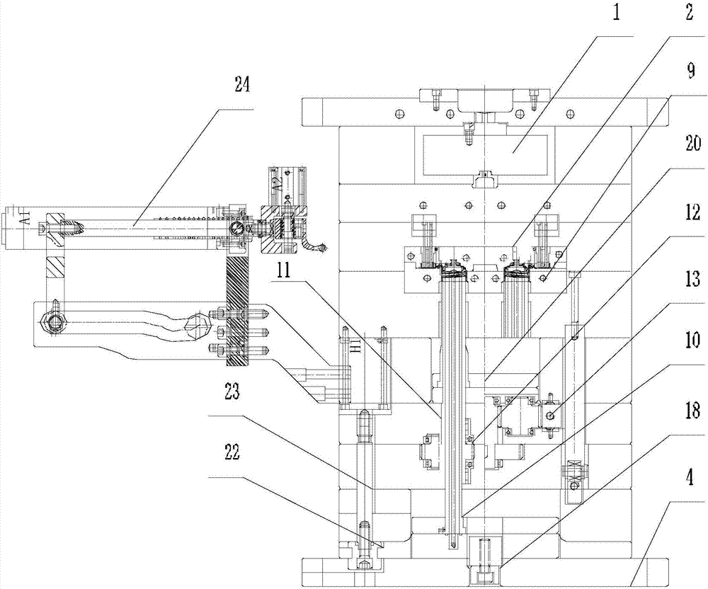
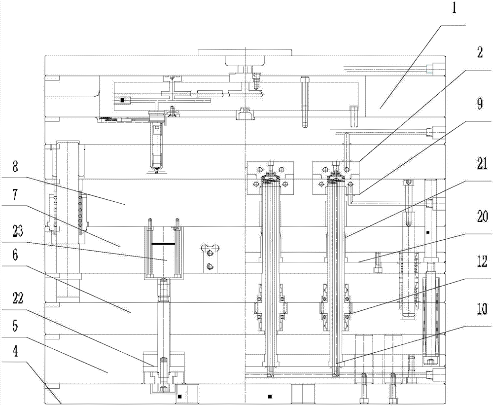
[0024] Such as Figure 1-4 Shown, a kind of injection mold of deep screw bottle cap comprises upper mold 1 and lower mold 3, and upper mold 1 is provided with several upper molding inserts 2, and upper molding insert 2 is provided with upper molding groove, and upper mold 1 Injection channels leading to each upper molding groove are provided in the upper mold 1, and upper cooling channels for cooling each upper molding insert 2 are arranged in the upper mold 1;

[0025] The lower mold 3 includes a lower base 4, and the lower base 4 is sequentially provided with a lower mounting seat 5, a transmission seat 6, an upper mounting seat 7, and a lower forming mold 8, and the lower forming mold 8 corresponds to each upper forming insert 2 A lower mold insert 9 is detachably provided at the bottom of the lower mold insert 9, and a lower molding groov...


PUM


Abstract

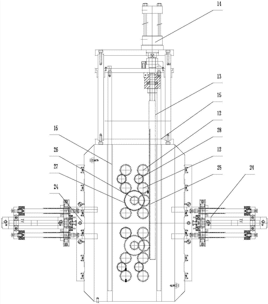
The invention discloses an injection mold which is used for a deep-thread bottle cap and is convenient and fast to demold. The injection mold comprises an upper mold body and a lower mold body. The lower mold body comprises a lower base. A lower mounting seat, a transmission seat, an upper mounting seat and a lower forming mold are sequentially arranged on the lower base from bottom to top. Lower die inserts are detachably arranged on the portions, corresponding to all upper forming inserts, in the lower forming mold. A lower forming groove is formed in each lower mold insert. A forming hole allowing the corresponding forming core mold to penetrate is formed in the bottom of each lower mold insert. All the forming core molds movably penetrate the lower mounting seat, the transmission seat, the upper mounting seat, the lower forming mold and the lower mold inserts. A spline is arranged in the middle of each forming core mold. Each spline is sleeved with a drive gear. A rack for driving the drive gears to rotate is movably arranged in a lower transmission seat in a penetrating manner. A synchronous air cylinder for driving the rack to move back and forth is arranged on the lower transmission seat. A transmission mechanism for connecting the rack with the drive gears is arranged in the transmission seat.

Description

technical field [0001] The invention relates to an injection mold for a bottle cap with deep threads. Background technique [0002] Some injection molds for threaded bottle caps push the bottle cap through the spring in the mold after the bottle cap is injection molded, so that the bottle cap is unscrewed from the mandrel under the action of the spring force, but the injection mold with this structure is used for screw thread When forming a deep cap, it will be difficult to remove the cap. Contents of the invention [0003] The technical problem to be solved by the present invention is to provide an injection mold for deep-threaded bottle caps that is easy and quick to remove from the mold. [0004] In order to solve the above-mentioned technical problems, the technical solution adopted in the present invention is: an injection mold for a deep threaded bottle cap, comprising an upper mold and a lower mold, the upper mold is provided with several upper molding inserts, and...

Claims


Application Information

Patent Timeline
Patent Type & Authority Applications(China)
IPC IPC(8): B29C45/44B29C45/32B29L31/56
CPCB29C45/32B29C45/4005B29C45/44B29L2031/56
Inventor 陈祝君杨波
Owner 张家港市天江精密模具制造有限公司
Learn More