
Induction cooker coil disc and processing technology thereof

A processing technology and a technology for a coil disk, applied to the field of an induction cooker coil disk and its processing technology, can solve problems such as inability to effectively control magnetic field leakage, limit induction heating efficiency, troublesome coil disk installation, etc., and achieve overall cost increase, installation process simplification, simple structure

Pending Publication Date: 2017-08-11
LESHAN NORMAL UNIV
View PDF13 Cites 1 Cited by
  • Summary
  • Abstract
  • Description
  • Claims
  • Application Information

AI Technical Summary

Problems solved by technology

Although the induction cooker coil plate with a straight magnetic strip is simple in structure, easy to manufacture, low in cost, and good in versatility, the magnetic strip must be fixed on the upper or lower surface of the engineering plastic bracket with high-temperature-resistant insulating silica gel or resin. At the same time, insulating tape is used to reinforce and isolate, so the coil plate of the induction cooker with this structure has always had the problem that the installation process is very troublesome, which makes the installation of the coil plate more troublesome in the production and manufacture of the induction cooker, the process is complicated, the process is more, and the production efficiency is affected. Moreover, the single shape and simple structure of the magnetic strip limit the further improvement of the induction heating efficiency, and at the same time, it is impossible to effectively control the magnetic field leakage

Method used


Image

  • Induction cooker coil disc and processing technology thereof
  • Induction cooker coil disc and processing technology thereof

Examples


Embodiment Construction

[0024] The present invention will be further described below in conjunction with the drawings.

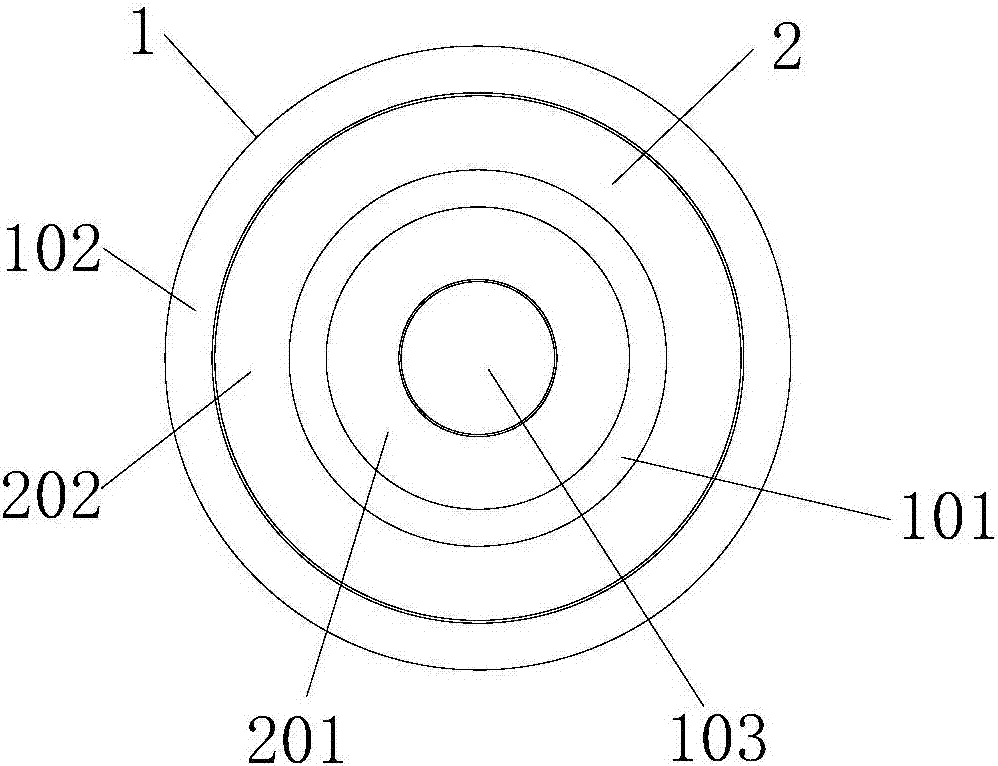
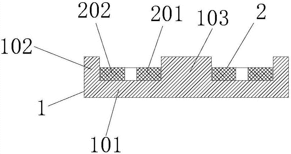
[0025] Such as Figure 1 to 2 As shown, the induction cooker coil plate includes a magnetic core frame 1 and a coil winding plate 2. The magnetic core frame 1 includes a circular chassis 101, and an upward annular flange is provided on the outer edge of the upper surface of the circular chassis 101 102. A support column 103 is provided at the center of the upper surface of the circular chassis 101, the coil winding disk 2 is sleeved on the support column 103, and the coil winding disk 2 is located between the annular flange 102 and the support column 103, so The circular chassis 101, the annular flange 102, and the support column 103 are an integrated structure, and the magnetic core frame 1 is integrally cast with magnetic materials and engineering plastics. The magnetic core frame 1 of the induction cooker coil plate is made of magnetic materials and engineering plastics. Such a ma...


PUM


Abstract

The invention discloses an induction cooker coil disc capable of simplifying an installation process and improving induction heating efficiency and a processing technology thereof. The induction cooker coil disc comprises a magnetic core framework and a coil winding disc, wherein the magnetic core framework comprises a round bottom disc, an upward annular flange is arranged at the edge of the outer side of an upper surface of the round bottom disc, a support post is arranged at the center of the upper surface of the round bottom disc, the coil winding disc sleeves the support post, the annular flange, the bottom disc and the support post are of an integrated structure, and the magnetic core framework is formed by integratedly pouring a magnetic material and engineering plastic. The magnetic core framework has a support effect of a support and also has an electromagnetic shielding effect of a magnetic strip, so that the installation process of the coil disc is greatly simplified, the total cost is not increased a lot, and the induction cooker coil disc is convenient to install and maintain; and moreover, the integrated magnetic core framework structure is simple in structure and is easy to manufacture, the installation process is simplified, the induction heating effect of an induction cooker can be greatly improved, and the induction cooker coil disc is suitable for promotion and application in the field of household appliances.

Description

Technical field [0001] The invention belongs to the field of household appliances, and specifically relates to an induction cooker coil plate and its processing technology. Background technique [0002] The induction cooker is an electric heating device that uses the eddy current generated by the electromagnetic induction principle to heat the pot. Its heating device is an induction cooker coil plate. The electromagnetic radiation also mainly comes from the coil plate. The coil plate includes a bracket, a magnetic strip, and a coil. Most of the coil plates of the existing induction cooker use in-line magnetic strips, which are radiatedly pasted above or below the coil support for electromagnetic shielding. Although the inline magnetic stripe coil plate of the induction cooker is simple in structure, easy to manufacture, low in cost, and good in versatility, the magnetic strip must be fixed on the upper or lower surface of the engineering plastic bracket with high-temperature insu...

Claims


Application Information

Patent Timeline
Patent Type & Authority Applications(China)
IPC IPC(8): H05B6/36
CPCH05B6/36H05B2206/022
Inventor 童强周大鹏何光普黄川邓迟
Owner LESHAN NORMAL UNIV
Learn More