
Hydraulic gearshift of tractor

A technology for shifting devices and tractors, applied in the direction of mechanical control devices, transmission device control, mechanical equipment, etc., can solve problems such as operational errors and high labor intensity, and achieve the effect of accurate action and light shift operation

Inactive Publication Date: 2017-08-08
SHANDONG WEIFANG LUZHONG TRACTOR
View PDF6 Cites 7 Cited by
  • Summary
  • Abstract
  • Description
  • Claims
  • Application Information

AI Technical Summary

Problems solved by technology

This requires a combination of multiple operating handles to achieve shifting. The driver needs to frequently operate each shifting handle, which is labor-intensive and prone to operational errors.

Method used


Image

  • Hydraulic gearshift of tractor
  • Hydraulic gearshift of tractor
  • Hydraulic gearshift of tractor

Examples


Embodiment Construction

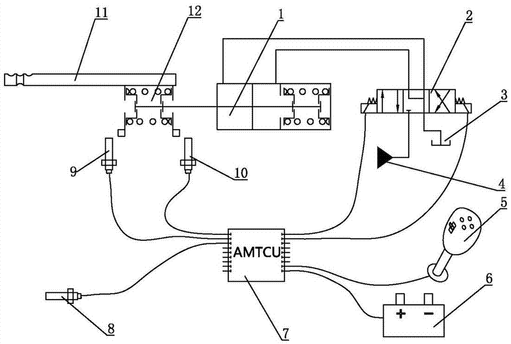
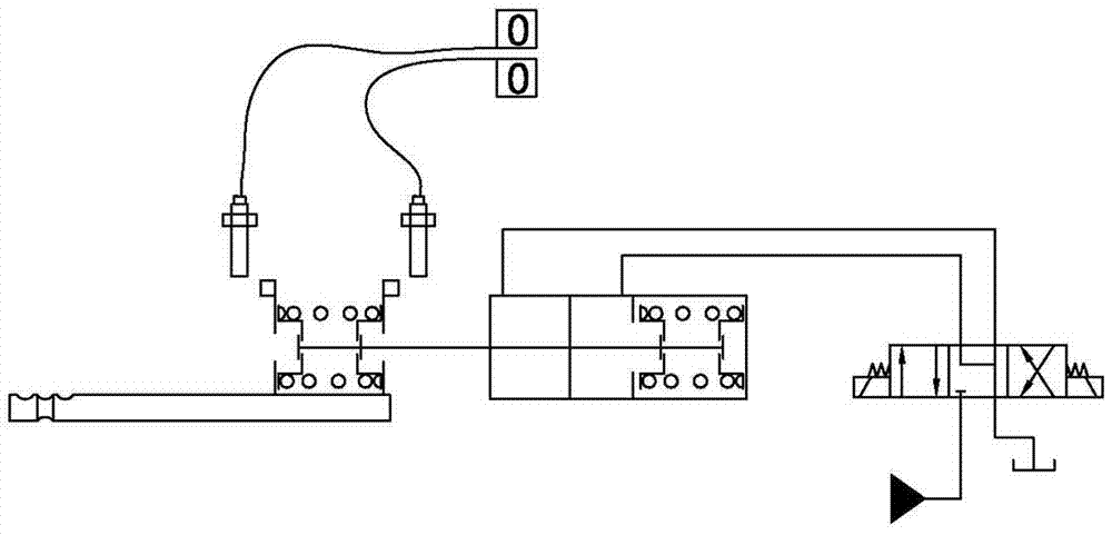
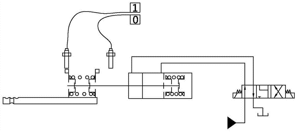
[0014] Such as figure 1 As shown, the tractor hydraulic shift device of the present invention includes a shift handle 5, a shift lever 11 and a clutch. A handle position sensor is installed on the shift handle 5 to detect the position information of the shift handle 5 in different gears. The handle position sensor can be a micro switch or other sensors such as travel switches. The signal output end of the handle position sensor is connected to the shift signal input end of the shift controller 7 to transmit the position state information of the shift handle 5 to the shift controller 7 .

[0015] A clutch position sensor 8 is installed on the clutch to detect whether the clutch is in a disengaged state. The signal output end of the clutch position sensor 8 is connected to the clutch signal input end of the shift controller 7, and the clutch position sensor can adopt a micro switch or a travel switch to judge whether the clutch is disengaged by the on and off of the switch. Th...


PUM


Abstract

The invention relates to technical field of manufacturing of tractors, particularly to a hydraulic gearshift of a tractor. The hydraulic gearshift comprises a gear shifting handle, a fork shifting rod and a clutch, wherein a handle position sensor connected to a gear shifting controller is mounted on the gear shifting handle; a clutch position sensor connected to the gear shifting controller is mounted on the clutch; a signal output end of the gear shifting controller is connected with a control end of a gear shifting electromagnetic valve and is used for controlling the movement of the gear shifting electromagnetic valve; the fork shifting rod is connected with a hydraulic cylinder in a transmission manner; the gear shifting electromagnetic valve is connected with an oil circuit of the hydraulic cylinder in series. According to the gearshift, the fork shifting rod is pushed to move by the hydraulic cylinder instead of manpower, so that the gear shifting operation is light and convenient, and the movement is accurate; the gear shifting controller is configured to write a corresponding gear shifting program, so that sequencing gear shifting and automatic gear shifting can be realized.

Description

technical field [0001] The invention relates to the technical field of tractor manufacturing, in particular to a tractor hydraulic shifting device. Background technique [0002] At present, the shifting device of the tractor all adopts the manual shift mechanism that the shift lever directly controls the shift fork to realize the gear meshing. For large and heavy-duty tractors, the sliding resistance of the gearbox gears is relatively large, and manual shifting is very difficult; in addition, the clutch is required to cooperate when the gearbox is shifted, and the shift fork is only allowed when the clutch is completely disengaged. Push the gear to shift gears, but the existing manual gear shifting mechanism does not have a corresponding locking device. When the clutch fails or the clutch is not separated due to an operation error, the gear shifting is easy to damage the gear and cause the gearbox to be damaged. Existing tractors mainly use conventional gears, synchronizers...

Claims


Application Information

Patent Timeline
Patent Type & Authority Applications(China)
IPC IPC(8): F16H59/02F16H61/40F16H61/04F16H63/32F16H63/34
CPCF16H59/02F16H61/04F16H61/40F16H63/32F16H63/34
Inventor 韩晓荣徐存款刘风平孟祥友韩密密李华龙
Owner SHANDONG WEIFANG LUZHONG TRACTOR
Learn More