


Quick Research
Generate reliable direction feasibility study reports for your R&D in just a few steps.

Technical Q&A
Discover and master advanced knowledge NOW. Basics, ideas, possibilities, all at once.

Find Solutions
As an expert in R&D theories, this can generate solutions to your technical problems instantly.

Evaluate Feasibility
Analyze your overall solution with one click, know your potential R&D risks in advance.

Monitor Landscape
Get weekly tech updates, stay abreast of the latest tech innovations and key insights.
An impeller for hydroelectric power generation
An impeller and water conservancy technology, applied in the field of water conservancy equipment and hydropower generation, can solve the problems of left and right shaking, small dead weight, high maintenance rate, etc., and achieve the effect of stable speed
- Summary
- Abstract
- Description
- Claims
- Application Information
AI Technical Summary
Problems solved by technology
Method used
Image

Examples
Embodiment 1
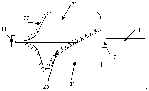
[0028] An impeller for hydroelectric power generation, including an impeller shaft and impeller blades;
[0029] One end of the impeller shaft is connected to the top bearing, the other end is connected to the end bearing, and is coaxially connected to the transmission shaft at the end.
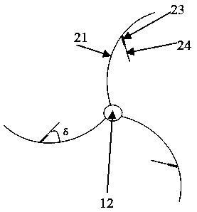
[0030] There are 5 impeller blades, all of which take the entire length of the impeller shaft as the contact part and extend outward in an arc shape, and the width of each impeller blade gradually increases from the top of the impeller shaft to the width at the end of the impeller shaft widest.
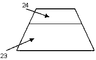
[0031] Inside the arc of each impeller blade, a speed reduction plate is arranged in reverse. The speed reduction plate includes a root portion of the speed reduction plate and a head portion of the speed reduction plate. The root portion of the speed reduction plate is fixedly connected to the impeller blade. The width of the root of the speed reduction plate is greater than the width of the head o...
Embodiment 2
[0040] Such as Figure 1~Figure 3 shown.
[0041] An impeller for hydroelectric power generation, including an impeller shaft and impeller blades;
[0042] One end of the impeller shaft is connected to the top bearing, the other end is connected to the end bearing, and is coaxially connected to the transmission shaft at the end.
[0043] There are 3 impeller blades, all of which take the entire length of the impeller shaft as the contact part and extend outward in an arc shape, and the width of each impeller blade gradually increases from the top of the impeller shaft to the width at the end of the impeller shaft widest.
[0044] Inside the arc of each impeller blade, a speed reduction plate is arranged in reverse. The speed reduction plate includes a root portion of the speed reduction plate and a head portion of the speed reduction plate. The root portion of the speed reduction plate is fixedly connected to the impeller blade. The width of the root of the speed reduction ...
Embodiment 3
[0060] An impeller for hydroelectric power generation, including an impeller shaft and impeller blades;
[0061] One end of the impeller shaft is connected to the top bearing, the other end is connected to the end bearing, and is coaxially connected to the transmission shaft at the end.
[0062] There are 3 impeller blades, all of which take the entire length of the impeller shaft as the contact part and extend outward in an arc shape, and the width of each impeller blade gradually increases from the top of the impeller shaft to the width at the end of the impeller shaft widest.
[0063] Inside the arc of each impeller blade, a speed reduction plate is arranged in reverse. The speed reduction plate includes a root portion of the speed reduction plate and a head portion of the speed reduction plate. The root portion of the speed reduction plate is fixedly connected to the impeller blade. The width of the root of the speed reduction plate is greater than the width of the head o...
PUM
 Abstract
Description
Claims
Application Information
 - R&D Engineer
- R&D Manager
- IP Professional
- Industry Leading Data Capabilities
- Powerful AI technology
- Patent DNA Extraction
Browse by: Latest US Patents, China's latest patents, Technical Efficacy Thesaurus, Application Domain, Technology Topic, Popular Technical Reports.
© 2024 PatSnap. All rights reserved.Legal|Privacy policy|Modern Slavery Act Transparency Statement|Sitemap|About US| Contact US: help@patsnap.com