
Electronic device and switching method for working mode thereof

A working mode and electronic device technology, applied in the field of working mode switching, can solve the problems of dragging the wake-up speed of electronic devices and huge initialization programs, etc.

Inactive Publication Date: 2017-08-04
ALICORP
View PDF7 Cites 4 Cited by
  • Summary
  • Abstract
  • Description
  • Claims
  • Application Information

AI Technical Summary

Problems solved by technology

In particular, as the design of the system chip becomes more and more complex, the initialization program from the hardware core becomes larger and larger, which will inevitably seriously hinder the speed of waking up the electronic device.

Method used


Image

  • Electronic device and switching method for working mode thereof
  • Electronic device and switching method for working mode thereof
  • Electronic device and switching method for working mode thereof

Examples


Embodiment Construction

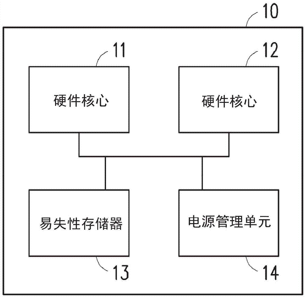
[0018] figure 1 is a schematic diagram of an electronic device according to an embodiment of the present invention. Hereinafter, the term coupled includes direct or indirect electrical connection.

[0019] Please refer to figure 1 , the electronic device 10 at least includes a hardware core 11 , a hardware core 12 , a volatile memory 13 and a power management unit 14 . The hardware core 11 is coupled to the hardware core 12 . The hardware core 11 and the hardware core 12 respectively include at least one processor.

[0020] In this embodiment, the hardware architectures of the hardware core 11 and the hardware core 12 are different. The hardware core 11 is the main hardware core of the electronic device 10 , and the hardware core 12 is the secondary hardware core of the electronic device 10 . For example, the hardware computing capability of the hardware core 11 is higher than that of the hardware core 12 . Alternatively, in another embodiment, the hardware core 11 and t...


PUM


Abstract

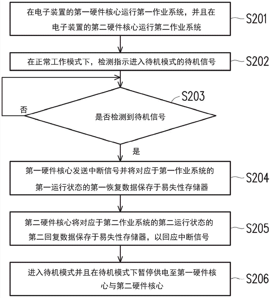
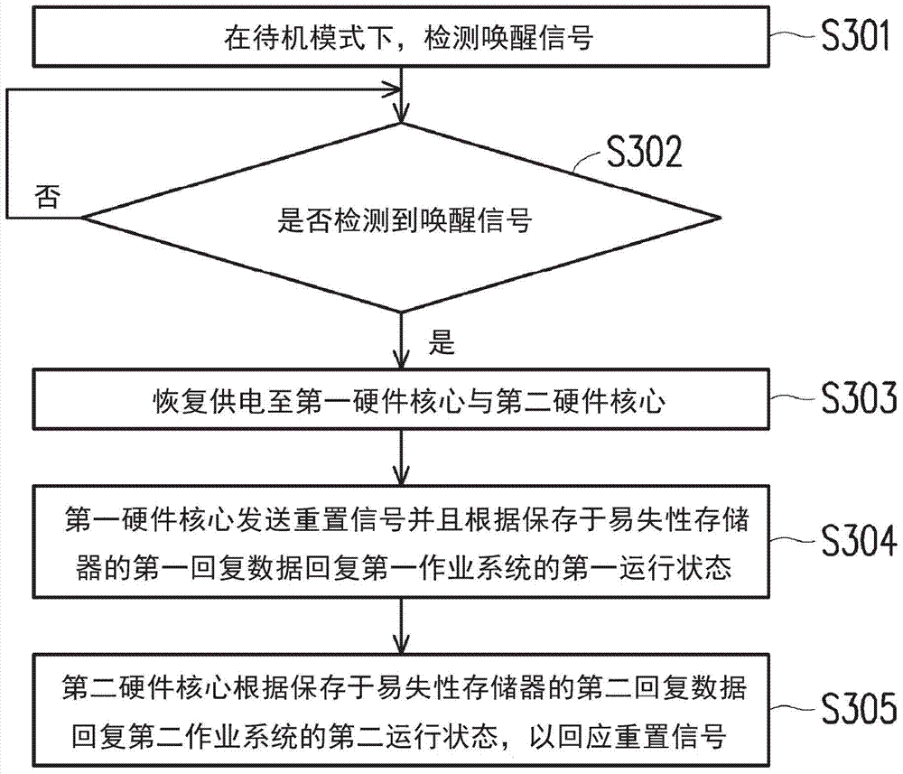
Provided are an electronic device and a switching method for working modes thereof. The method comprises: respectively operating a first work system and a second work system on a first hardware core and a second hardware core of an electronic device; under a normal work mode, the first hardware core detecting a standby signal which indicates to enter a standby mode; the first hardware core sending an interrupt signal, and storing first reply data which is corresponding to the first operating state of the first work system to volatile memory of the electronic device, to respond to the standby signal; the second hardware core storing second reply data of the second operating state of the second work system to the volatile memory, to respond to the interrupt signal; entering the standby mode, and pausing power supply for the first hardware core and the second hardware core under the standby mode. Thus, awakening speed of the electronic device is improved.

Description

technical field [0001] The present invention relates to a working mode switching technology, and in particular to an electronic device and a working mode switching method thereof. Background technique [0002] Generally speaking, in order to increase the computing speed of the electronic device, the electronic device may be installed with a SoC having multiple hardware cores. Under the architecture with multiple hardware cores, each hardware core will run a dedicated operating system, and the operating systems can operate independently or coordinate with each other. Generally speaking, the computing power of the main (Master) hardware core will be higher than that of the slave (Slave) hardware core. Therefore, the main hardware core is often used to run the main operating system, while the slave hardware core is used to run the secondary hardware core. operating system. For example, the main operating system is responsible for maintaining the overall operation of the elect...

Claims


Application Information

Patent Timeline
Patent Type & Authority Applications(China)
IPC IPC(8): G06F9/46
CPCG06F9/461
Inventor 张腾
Owner ALICORP
Learn More