A vibrating wire type miniature strain gauge

A strain gauge and vibrating wire technology, which is applied in the field of geotechnical and engineering structure safety monitoring, can solve the problems of low measurement accuracy and large shape and volume.

Pending Publication Date: 2017-08-04
CHINA GEOKON INSTR
View PDF6 Cites 0 Cited by
  • Summary
  • Abstract
  • Description
  • Claims
  • Application Information

AI Technical Summary

Problems solved by technology

[0003] The present invention aims at the problems that the traditional vibrating wire strain gauge has a large shape and low measurement accuracy, and provides a small vibrating wire strain gauge, which adopts a centralized structure design, is small in size and is especially suitable for use in space-constrained applications. Deformation monitoring has the advantages of high measurement accuracy, long service life, and strong environmental adaptability, and is suitable for wide application in engineering

Method used


Image

  • A vibrating wire type miniature strain gauge
  • A vibrating wire type miniature strain gauge

Examples


Embodiment Construction

[0025] The present invention will be described below in conjunction with the accompanying drawings.

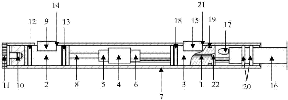
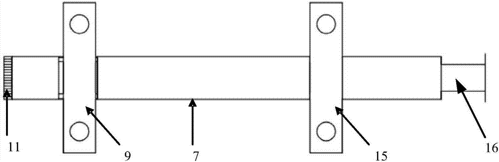
[0026] The present invention relates to a small vibrating wire strain gauge, which adopts a centralized structure design and is used to measure the strain in steel structures and structures with small spacing. The preferred structure is as follows figure 1As shown, it includes steel string 1, first end block 2, second end block 3, coil 4, first magnet 5, second magnet 6 and protective outer cylinder 7, steel string 1, coil 4, first magnet 5 and The second magnets 6 are all arranged in the protective outer cylinder 7, and the first end block 2 and the second end 3 are respectively arranged inside the two ends of the protective outer cylinder 7. The above-mentioned structure can avoid the steel string 1, the first end block 2 , the second end block 3 , the coil 4 , the first magnet 5 and the second magnet 6 are in direct contact with the measuring object, reducing the wear of th...


PUM


Abstract

The invention relates to a vibrating wire type miniature strain gauge comprising a steel wire, a first end block, a second end block, a coil, a first magnet, a second magnet and a protective outer cylinder; the steel wire, the coil, the first magnet and the second magnet are all arranged inside the protective outer cylinder; the first end block and the second end block are respectively arranged inside the two ends of the protective outer cylinder; the first end block is connected with one end of the steel wire; the second end block is connected with the other end of the steel wire; and the coil is arranged on the outer side of the steel wire; the coil, the first magnet and the second magnet provide signal excitations and signal outputs for the strain gage; and the protective outer cylinder, the steel wire, the first end block, the second end block, the coil, the first magnet and the second magnet form an integrated structure. The vibrating wire type miniature strain gauge adopts centralized structure design, is small in size and is particularly suitable for deformation monitoring in space-constrained applications, and has advantages such as high measurement accuracy, a long life cycle, strong environmental adaptability and being suitable for extensive use in engineering.

Description

technical field [0001] The invention relates to the technical field of rock soil and engineering structure safety monitoring, in particular to a vibrating wire type small strain gauge. Background technique [0002] The vibrating wire strain gauge is a strain gauge that uses the vibrating wire principle for measurement. Its biggest advantages are simple structure, reliable operation, and the output signal is a standard frequency signal, which is very convenient for computer processing. The traditional vibrating wire strain gauge structure is to install steel strings in an outer cylinder. Magnets are arranged at both ends of the coil. The disadvantage of the traditional vibrating wire strain gauge is that it is a separate structure and has a relatively large external volume. When measuring, it needs to assemble the various parts first. The process is cumbersome, and it takes up a lot of space. It cannot be used in space-constrained applications. It is not suitable for small ...

Claims


Application Information

Patent Timeline
IPC IPC(8): G01B17/04
CPCG01B17/04
Inventor 庄治洪吴其均程杜斌凡强
Owner CHINA GEOKON INSTR
Why Eureka
Try Eureka