
Rotary lamp

A technology for lamps and turntables, which is applied to cooling/heating devices of lighting devices, outdoor lighting, lighting applications, etc., can solve problems such as poor practicability, poor lighting effects, complex structure and wiring, etc.

Pending Publication Date: 2017-08-04
PR LIGHTING
View PDF3 Cites 7 Cited by
  • Summary
  • Abstract
  • Description
  • Claims
  • Application Information

AI Technical Summary

Problems solved by technology

However, most of the control devices of the existing stage rotating lamps have complex structures and wiring, and are prone to line failures during use, and as the number of maintenance increases, the lighting effect will gradually deteriorate, and the practicability is not strong.

Method used


Image

  • Rotary lamp
  • Rotary lamp
  • Rotary lamp

Examples


Embodiment Construction

[0089] Embodiments of the present invention will be described in detail below.

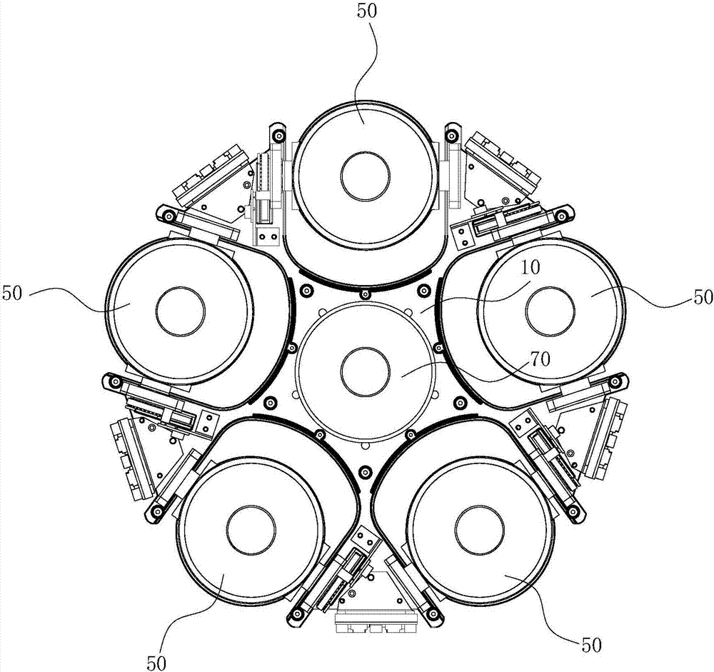
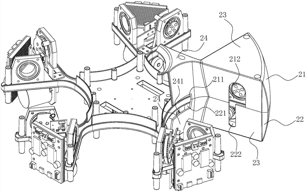
[0090] Such as Figure 1 to Figure 12 As shown, the rotating lamp includes a rotating lamp turntable and a lamp unit 50, the rotating lamp turntable is provided with a lamp unit installation position, and at least two control device installation parts 12 are arranged in the rotating lamp turntable, and the control device installation parts 12 are arranged on the lamp unit On both sides of the installation position, the control device installation part 12 located on one side of the lamp unit installation position is provided with a circuit board 40 and a positioning piece, and the control device installation part 12 located on the other side of the lamp unit installation position is provided with a drive motor 30 and The transmission part, the driving motor 30 is connected with the transmission part;

[0091] The lamp unit 50 is arranged at the installation position of the lamp unit. The lamp unit...


PUM


Abstract

The invention discloses a rotary lamp which comprises a rotary lamp rotating plate and a lamp unit. The rotary lamp rotating plate is provided with a lamp unit mounting site and internally provided with at least two control device mounting portions. The control device mounting portion on one side of the lamp unit mounting site is provided with a circuit board and a positioning piece. The control device mounting portion on the other side of the lamp unit mounting site is provided with a drive motor and a driving piece which are in driving connection. The lamp unit is arranged at the lamp unit mounting site. A first connection site of the lamp unit is connected with the positioning piece and provided with a through hole communicating with the inside of the lamp unit. The circuit board is provided with a connection wire with one end connected with the circuit board and the other end penetrating through the through hole and electrically connected with the lamp unit. A second connection side of the lamp unit is connected with the driving piece which drives the lamp unit to rotate. According to the rotary lamp, control devices are simple in structure and circuit, circuit faults are not prone to occurring, and practicability is high.

Description

technical field [0001] The invention relates to the technical field of lamps, in particular to a rotating lamp. Background technique [0002] With the continuous development of science and technology, lamps and lanterns have been widely used in various fields. The styles are also varied. [0003] In most stage performances, performing arts venues will apply a large number of stage lamps, and use various stage lamps with different stage lighting effects to achieve the stage performance effect required by the live environment. However, most of the control devices of the existing stage rotating lamps have complex structures and wiring, and are prone to circuit failures during use. Moreover, as the number of maintenance increases, the lighting effect will gradually deteriorate, and the practicability is not strong. Contents of the invention [0004] The purpose of the present invention is to provide a rotating lamp. The structure and circuit of the rotating lamp control devi...

Claims


Application Information

Patent Timeline
Patent Type & Authority Applications(China)
IPC IPC(8): F21S10/06F21V21/30F21V21/15F21V29/76F21V29/83F21W131/105F21W131/406
CPCF21S10/063F21V21/15F21V21/30F21V29/76F21V29/83F21W2131/406F21W2131/105
Inventor 刘洪华王文浩
Owner PR LIGHTING
Learn More