Self-pressure-relief quick coupling and working method thereof

A self-relieving and fast technology, applied in the direction of mechanical equipment, couplings, etc., can solve the problems of cold plate scrapping, cold plate surface deformation, bulging, etc., achieve the effect of stable guidance and fast circulation

Active Publication Date: 2017-08-04
丹阳市裕桥精密元件有限公司
View PDF6 Cites 4 Cited by
  • Summary
  • Abstract
  • Description
  • Claims
  • Application Information

AI Technical Summary

Problems solved by technology

As the coolant fills the cold plate, the pressure of the expanded coolant increases sharply, causing the...

Method used


Image

  • Self-pressure-relief quick coupling and working method thereof
  • Self-pressure-relief quick coupling and working method thereof
  • Self-pressure-relief quick coupling and working method thereof

Examples


Embodiment 1

[0029] Embodiment 1 The self-relieving quick connector of this embodiment includes a male plug and a female plug that are plugged together (for the convenience of discussion, when the components in the male plug refer to the front end, it refers to the end close to the connection between the male plug and the female plug. The opposite end is the tail end; when the parts in the female plug refer to the tail end, it refers to the end near the connection between the male plug and the female plug, and the opposite end is the front end); figure 1 As shown, the male plug includes a first sleeve 11 of the male plug and a second sleeve 12 of the male plug. An annular connection portion 16 is arranged inside the first sleeve 11 of the male plug, and the tail end of the second sleeve 12 of the male plug is connected to the annular connection portion Threaded connection, so that a cylindrical cavity 19 is formed between the first sleeve 11 of the male plug and the second sleeve 12 of the ...

Embodiment 2

[0039] The working method of the self-relieving pressure quick connector as described in embodiment 1, comprises the steps:

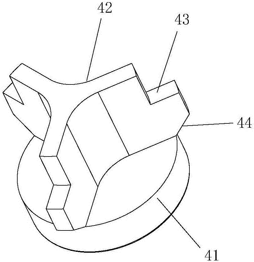
[0040] A. When not mated, the male plug is in a closed state, the first spring 14 supports the first valve core 4 to reach the front end of the second sleeve 12 of the male plug, and the annular side wall of the first sealing disc 41 and the second sleeve of the male plug The first annular sealing portion 18 of the cylinder 12 is sealed and fitted through the first O-ring 31; the female plug is in a closed state, and the second spring 24 supports the second valve core 5 to reach the tail end of the first sleeve 21 of the female plug, and at the same time The annular bracket 23 supporting the valve stem 61 moves to the side wall of the annular groove 25 close to the front end of the first sleeve 21 of the female plug, and is limited by the first retaining ring 23, and the outer wall of the second valve core 5 passes through the third O-shaped The sealing...


PUM


Abstract

The invention relates to a self-pressure-relief quick coupling and a working method of the self-pressure-relief quick coupling. The self-pressure-relief quick coupling comprises a male plug and a female plug which are matched in a plugged mode. The male plug and the female plug are in sealed fit with annular sealing portions of sleeves through a movable first valve element and a movable second valve element correspondingly, and the structure is simple. The third annular sealing portion of the second valve element is provided with a pressure relief channel, and an inlet of the pressure relief channel is formed in an annular inner wall. The position relation between a second O-shaped sealing ring and the inlet of the pressure relief channel is changed by moving a second sealing disc, pressure relief of the female plug is effectively achieved, sliding fit between the second sealing disc and the annular inner wall of the second valve element is not affected, and the phenomenon that a valve rod is clamped and cannot be reset is avoided. By means of fit between an annular groove and an annular support, the movement stroke of the valve rod is effectively limited, and the valve rod is prevented from being disengaged from the female plug first sleeve.

Description

technical field [0001] The invention relates to the technical field of pipeline auxiliary equipment, in particular to a self-relieving pressure quick connector and a working method thereof. Background technique [0002] Quick connectors include hydraulic quick connectors and various fluid quick connectors. It is a connection device that quickly connects or disconnects pipelines and realizes quick disassembly. The quick connector consists of two parts, a male plug and a female plug. The male plug and the female plug are each equivalent to a one-way valve with a spool inside. When not inserted, the one-way valve is closed under the action of the spring force. The female plugs are independently sealed; after the male plug is inserted into the female plug, the spring is compressed, and the spools of the male plug and the female plug are pushed open at the same time, the two pipelines are connected, and the fluid can flow. When the above-mentioned quick connectors are used in a ...

Claims


Application Information

Patent Timeline
IPC IPC(8): F16L37/367
CPCF16L37/367
Inventor 蒋于良李中和杜振
Owner 丹阳市裕桥精密元件有限公司
Why Eureka
Try Eureka