Convenient drawer type power cabinet

A technology of drawer type and power cabinet, which is applied in the direction of pull-out switch cabinets, electrical components, switchgear, etc., and can solve problems such as laborious, unsatisfactory, and unstable force

Active Publication Date: 2017-08-01
山东恒东实业集团有限公司
View PDF5 Cites 4 Cited by
  • Summary
  • Abstract
  • Description
  • Claims
  • Application Information

AI Technical Summary

Problems solved by technology

When there are many devices in the drawer, the pull out of the drawer is still to directly pull the handle on the drawer panel, which is more laborious, and it is easy to cause unstable force by manually pushing and pulling the handle, and it is easy to cause a large impact when pulling out and pushing This leads to a large safety hazard, and the traditional self-control drawer push device can only control the in and out movement of one drawer at a time, and cannot realize selective or simultaneous removal of drawers, and cannot meet various needs during maintenance.

Method used


Image

  • Convenient drawer type power cabinet
  • Convenient drawer type power cabinet
  • Convenient drawer type power cabinet

Examples


Embodiment Construction

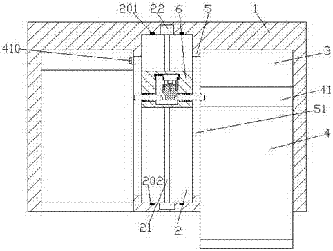
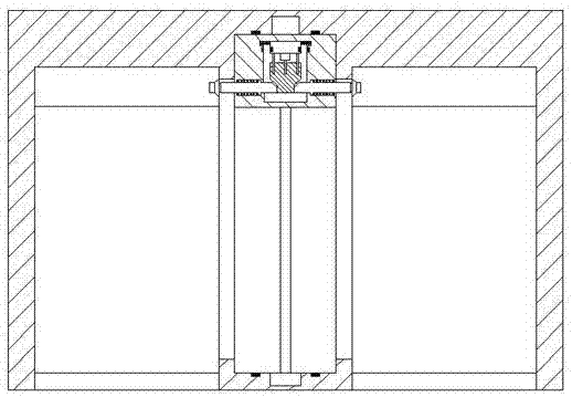
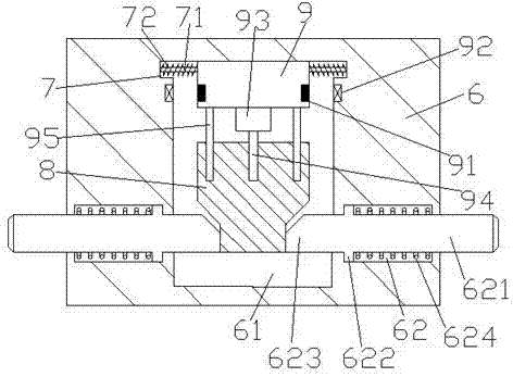
[0017] Such as Figure 1-Figure 5 As shown, a convenient drawer-type power cabinet of the present invention includes a cabinet body 1, and the cabinet body 1 is symmetrically provided with accommodating cavities 3 and driving cavities 2 between the accommodating cavities 3. A partition plate 5 with a chute 51 is provided between the drive chamber 2 and the accommodation chamber 3, a drawer 4 is provided in the accommodation chamber 3, a rear panel 41 is provided on the rear end of the drawer 4, and the drive A first screw rod 21 is arranged in the cavity 2, and an operating mechanism 6 is threadedly connected to the first screw rod 21. An operating chamber 61 is arranged inside the operating mechanism 6, and two sides of the top of the operating chamber 61 are provided with oppositely arranged Groove 7, described groove 7 is provided with first guide rod 71, and described first guide rod 71 is provided with slide table 9 that slides and fits to connect left and right, describe...


PUM


Abstract

The invention discloses a convenient drawer type power cabinet which comprises a cabinet body. Accommodation cavities are symmetrically arranged in the cabinet body left and right, and a driving cavity is arranged between the accommodation cavities. Separation plates with chutes are arranged between the driving cavity and the accommodation cavities. A drawer is arranged in each accommodation cavity. A rear panel is arranged on the rear end face of each drawer. A first screw is arranged in the driving cavity. The first screw is threadedly connected with an operation mechanism. The operation mechanism is provided with an operation cavity. Opposite grooves are arranged on both sides of the top of the operation cavity. A first guide rod is arranged in each groove. Left and right sliding tables slidingly connected are arranged on each first guide rod. According to the invention, the convenient drawer type power cabinet has the advantages of simple structure; a number of drawing out modes are realized according to different requirements; and the overhaul speed and security of staff are improved.

Description

technical field [0001] The invention relates to the technical field of electric power, in particular to a convenient drawer-type power cabinet. Background technique [0002] Power drawers are often used in the field of power control. When there are many devices in the drawer, the pull out of the drawer is still to directly pull the handle on the drawer panel, which is more difficult, and it is easy to cause unstable force by manually pushing and pulling the handle, and it is easy to produce a large impact when pulling out and pushing As a result, there are relatively large safety hazards, and the traditional device for self-controlling drawer advancement can only control the in and out movement of one drawer at a time, cannot realize selective or simultaneous removal of drawers, and cannot meet various needs during maintenance. Contents of the invention [0003] The technical problem to be solved by the present invention is to provide a convenient drawer-type power cabine...

Claims


Application Information

Patent Timeline
Patent Type & Authority Applications(China)
IPC IPC(8): H02B11/127H02B11/173
CPCH02B11/127H02B11/173
Inventor 袁承宇
Owner 山东恒东实业集团有限公司
Why Eureka
Try Eureka