
Display panel and display device

A display panel and display area technology, applied in optics, instruments, electrical digital data processing, etc., can solve the problems that the frame of the display device cannot be further compressed, it is difficult to realize narrow frame design, and the signal wiring cannot be further compressed, etc., to achieve Achieve narrow bezel design, reduce the space of the bezel, and improve the effect of screen ratio

Inactive Publication Date: 2017-07-28
XIAMEN TIANMA MICRO ELECTRONICS
View PDF5 Cites 5 Cited by
  • Summary
  • Abstract
  • Description
  • Claims
  • Application Information

AI Technical Summary

Problems solved by technology

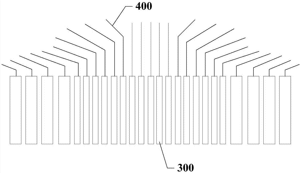
The signal traces 400 are distributed in a fan shape. Since the connecting pins 300 on the COF flexible circuit board have the same length, the signal traces connected to the connecting pins in the middle area still have room for compression, but the connecting pins located on the left and right sides have room for compression. The signal traces connected to the pins cannot be further compressed
Due to the lack of space for the signal traces connected to the connecting pins on the left and right sides, the frame of the display device cannot be further compressed, so it is difficult to achieve a narrow frame design

Method used


Image

  • Display panel and display device
  • Display panel and display device
  • Display panel and display device

Examples


Embodiment Construction

[0043] Certain terms are used, for example, in the description and claims to refer to particular components. Those skilled in the art should understand that hardware manufacturers may use different terms to refer to the same component. The specification and claims do not use the difference in name as a way to distinguish components, but use the difference in function of components as a criterion for distinguishing. As mentioned throughout the specification and claims, "comprising" is an open term, so it should be interpreted as "including but not limited to". "Approximately" means that within an acceptable error range, those skilled in the art can solve the technical problem within a certain error range and basically achieve the technical effect. In addition, the term "coupled" herein includes any direct and indirect electrical coupling means. Therefore, if it is described that a first device is coupled to a second device, it means that the first device may be directly elect...


PUM


Abstract

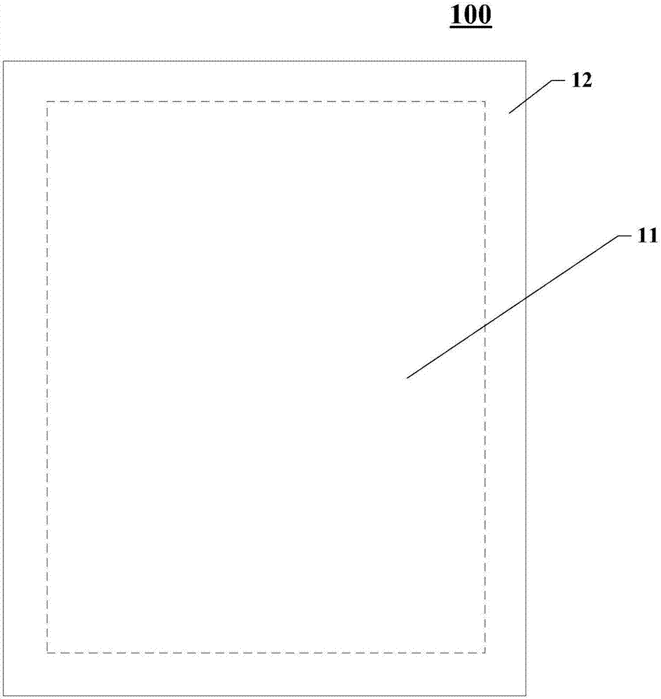
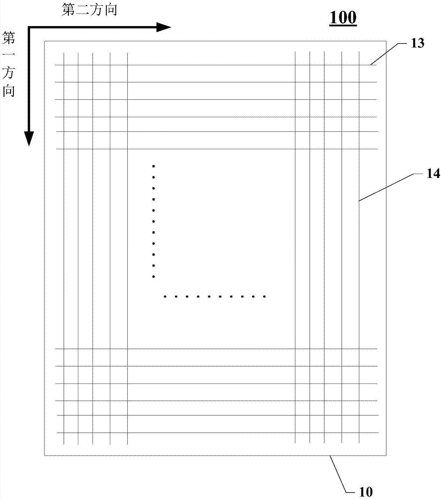
The invention discloses a display panel and a display device, and relates to the technical field of display. The display panel is provided with a display area and a non-display area surrounding the display area. The display panel comprises an array substrate, a plurality of gate lines, a plurality of data signal lines, a circuit board and a control chip, the gate lines and the data signal lines are arranged on the first surface of the array substrate, the gate lines are arranged in the first direction and extend in the second direction, and the data signal lines are arranged in the second direction and extend in the first direction. The circuit board is arranged on the first surface of the array substrate and comprises a first connecting pin set and second connecting pin sets located on the two sides of the first connecting pin set, and the length of the second connecting pin sets is smaller than that of the first connecting pin set. The control chip is arranged on the circuit board, electrically connected with the data signal lines through the first connecting pin set and / or the second connecting pin sets and electrically connected with the gate lines through the first connecting pin set and / or the second connecting pin sets. In this way, the frame width of the display device can be reduced, and narrow frame design of the display device can be achieved.

Description

technical field [0001] The present application relates to the field of display technology, in particular, to a display panel and a display device. Background technique [0002] As panel displays are more and more widely used, widescreen technology has become an important technical item. At the same time, the technology of narrow lower borders of display panels is also becoming more and more important. Advanced electronic products, especially portable electronic products, tend to be smaller in size. COF (chip on flexible, flexible chip) technology is an important technology to realize the miniaturization of electronic products. The so-called COF technology refers to designing the driver chip IC in a flexible material, and then folding the flexible material to the back of the display panel, so as to realize the miniaturization of the entire display device. [0003] figure 1 It is a structural schematic diagram of connecting pins on a COF flexible circuit board and signal le...

Claims


Application Information

Patent Timeline
IPC IPC(8): G02F1/1345G02F1/1362G02F1/1333G06F3/041
CPCG02F1/13338G02F1/13452G02F1/136286G06F3/041
Inventor 蔡寿金吴昊吴树茂朱绎桦贝亮亮陈国照周洪波沈柏平伍黄尧
Owner XIAMEN TIANMA MICRO ELECTRONICS
Learn More