Mechanical end tooth clutch

A clutch and mechanical technology, applied in the field of aero-engines, can solve problems such as short service life, high requirements for design, manufacturing and assembly, and poor reliability, and achieve long service life, low processing and manufacturing costs, and small dimensions

Active Publication Date: 2019-04-23
AECC HUNAN AVIATION POWERPLANT RES INST
View PDF9 Cites 0 Cited by
  • Summary
  • Abstract
  • Description
  • Claims
  • Application Information

AI Technical Summary

Problems solved by technology

[0005] The invention provides a mechanical end-tooth clutch to solve the technical problems of short service life, high requirements for design, manufacture and assembly, and poor reliability of existing overrunning clutches.

Method used


Image

  • Mechanical end tooth clutch
  • Mechanical end tooth clutch

Examples


Embodiment Construction

[0024] The embodiments of the present invention will be described in detail below with reference to the accompanying drawings, but the present invention can be implemented in many different ways defined and covered by the claims.

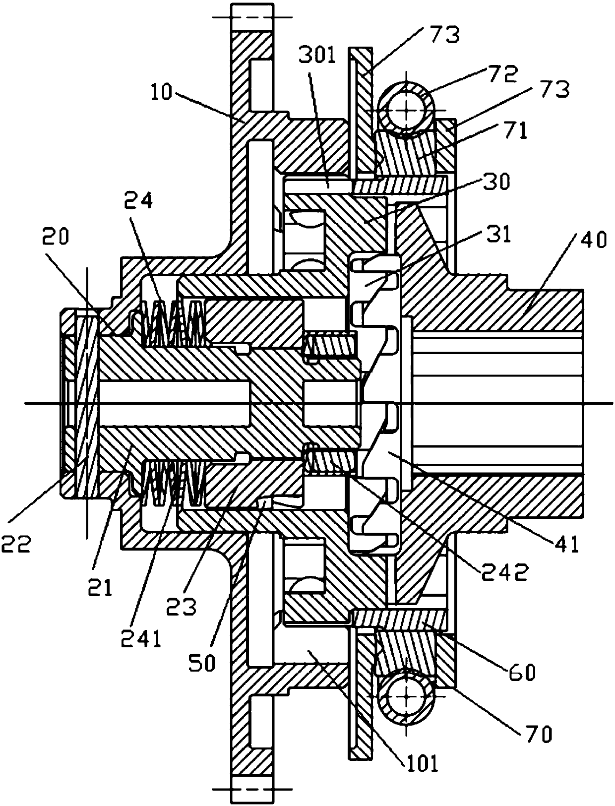
[0025] refer to figure 2 , the preferred embodiment of the present invention provides a mechanical end-tooth clutch, which is used to engage or separate the main transmission part (not shown) and the slave transmission part (not shown) in the speed reducer. The mechanical end-tooth clutch includes : the adapter plate 10 used to be connected with the main transmission parts, the adapter plate 10 is a hollow cylindrical structure, the first inner spline 101 is arranged on its inner circle, and the shaft hole of the adapter plate 10 is equipped with a tube Shaped adapter tube assembly 20 , the adapter tube assembly 20 is arranged coaxially with the adapter plate 10 and is fixedly connected with the adapter plate 10 . It also includes an input-end gea...


PUM


Abstract

The invention discloses a mechanical type end tooth clutch. The mechanical type end tooth clutch comprises an adapting disk. The inner circle face of the adapting disk is provided with a first internal spline. An adapting cylinder assembly is arranged in a shaft hole of the adapting disk. The adapting cylinder assembly is coaxial with the adapting disk. The mechanical type end tooth clutch further comprises an input end gear and an output end gear, wherein the input end gear and the output end gear are coaxial with the adapting cylinder assembly and are oppositely arranged, and input end teeth and output end teeth are arranged between the input end gear and the output end gear and used for transmission engagement during start and disengagement after starting. The outer circle of the input end gear is provided with a first outer spline. The first outer spline is used for being matched with the first inner spline when the input end teeth are meshed with the output end teeth. The adapting cylinder assembly is sleeved with the input end gear. The inner circle face of the input end gear is provided with a connecting structure used for being connected with the adapting cylinder assembly, so that when the adapting cylinder assembly rotates, the input end gear is pushed to move along the axis of input end gear, and when the output end gear drives the input end gear to rotate, the input end gear is made to move in the direction away from the output end gear along the axis of the input end gear.

Description

technical field [0001] The invention relates to the field of aero-engines, in particular to a mechanical end tooth clutch. Background technique [0002] Most of the clutches used in the existing starter reducers are overrunning clutches. The structural diagram of this type of clutch is shown in the attached drawing figure 1 As shown, it mainly includes outer ring 1 (outer jacket, usually used as active element), inner ring 2 (inner shaft, usually used as driven element), groups of diagonal braces 3, inner cage 4, outer cage 5, spring 6 and bearings, etc., when working, the torque is transmitted through the wedging effect between the inner ring 2 and the outer ring 1 of the set of diagonal braces 3 . [0003] When the rotation speed of the outer ring 1 in the counterclockwise direction is greater than the rotation speed of the inner ring 2, under the tension force of the spring 6 and the friction between the brace block 3 and the joint surface of the outer ring 1 and the inn...

Claims


Application Information

Patent Timeline
Patent Type & Authority Patents(China)
IPC IPC(8): F16D41/18
CPCF16D41/18
Inventor 赵建华雷衍斌陈国强郭丹刘飞明宁凤莲
Owner AECC HUNAN AVIATION POWERPLANT RES INST
Why Eureka
Try Eureka