Method and exhaust gas aftertreatment system for determining load of particle-filtering assembly

A technology of exhaust gas post-processing and equipment, which is applied in the direction of exhaust gas treatment, electronic control of exhaust gas treatment devices, diagnostic devices of exhaust gas treatment devices, etc., and can solve problems such as difficulties

Active Publication Date: 2017-07-28
ROBERT BOSCH GMBH
View PDF10 Cites 0 Cited by
  • Summary
  • Abstract
  • Description
  • Claims
  • Application Information

AI Technical Summary

Problems solved by technology

[0005] However, using this approach to accurately determine the load

Method used


Image

  • Method and exhaust gas aftertreatment system for determining load of particle-filtering assembly
  • Method and exhaust gas aftertreatment system for determining load of particle-filtering assembly
  • Method and exhaust gas aftertreatment system for determining load of particle-filtering assembly

Examples


Embodiment Construction

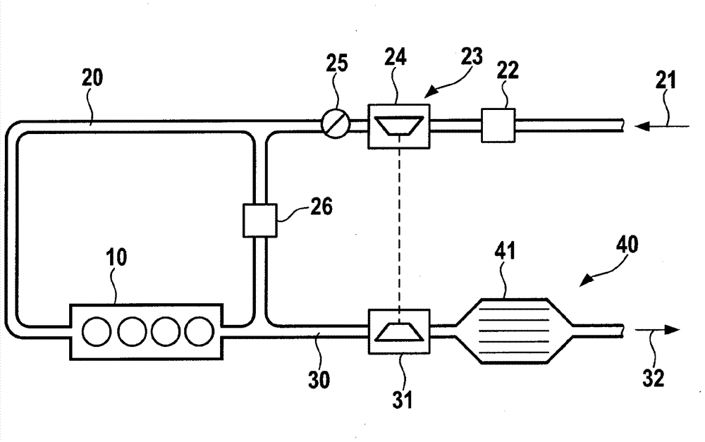
[0026] figure 1 Illustratively shows a simplified schematic diagram of an air and exhaust gas guide in a motor vehicle environment with an internal combustion engine 10 in which the method according to the invention can be applied. Before the supply air flow 21 is delivered via the compression stage 24 of the turbocharger 23 and the throttle valve 25 of the internal combustion engine 10, the supply air flow 21 first passes through the air quality sensor 22 through the air delivery passage 20. In the internal combustion engine 10, the air is converted in an exothermic manner together with the delivered fuel (not shown here). The generated exhaust gas can partly be re-transmitted to the supply air flow 21 via the exhaust gas recirculation 26. The remaining exhaust gas flow 32 is firstly guided via the exhaust gas turbine 31 of the turbocharger 23 via the exhaust duct 30 and then enters the exhaust gas aftertreatment device 40. A four-way catalyst 41 is arranged in the exhaust g...


PUM


Abstract

The invention relates to a method and exhaust gas aftertreatment system for determining a load of a particle-filtering assembly of an exhaust gas aftertreatment system (40), which is assigned to an internal combustion engine (10) in a motor vehicle, wherein the rotational speed of the internal combustion engine (10) is included. A method as well as an exhaust gas aftertreatment system for determining the loading state also in an ottomotor is achieved in that the loading state is determined based on an operating variable derived from the rotational speed of the internal combustion engine (10).

Description

Technical field [0001] The invention relates to a method for obtaining the load of the filter particle components of an exhaust gas aftertreatment device and a corresponding exhaust gas aftertreatment device which is assigned to an internal combustion engine in a motor vehicle, wherein the speed of the internal combustion engine is taken into account Inside. Background technique [0002] In the aftertreatment of exhaust gas from diesel motors in motor vehicles, particulate filters have been used in recent years in order to be able to comply with limit values ​​in terms of particulate emissions. Due to further tightening of the limit value, it may be necessary in the future that even the exhaust gas aftertreatment system in the Otto motor is equipped with a particulate filter. This is because especially in Otto motors with direct injection, that is, internal mixture formation, not only structural measures but also application measures are reaching their limits. From a system poi...

Claims


Application Information

Patent Timeline
IPC IPC(8): F01N9/00F02D41/02
CPCF01N9/002F02D41/0235F01N2900/1606F02D2200/101F01N11/002F02D41/2406F02D41/2432F01N2560/08F02D2200/0812F02D2200/1002Y02T10/40
Inventor A.达利奥斯D.莱吉泽克
Owner ROBERT BOSCH GMBH
Why Eureka
Try Eureka