


Quick Research
Generate reliable direction feasibility study reports for your R&D in just a few steps.

Technical Q&A
Discover and master advanced knowledge NOW. Basics, ideas, possibilities, all at once.

Find Solutions
As an expert in R&D theories, this can generate solutions to your technical problems instantly.

Evaluate Feasibility
Analyze your overall solution with one click, know your potential R&D risks in advance.

Monitor Landscape
Get weekly tech updates, stay abreast of the latest tech innovations and key insights.
Welding seam tracking system and welding seam tracking method
A technology of tracking system and welding torch, which is applied in the field of weld tracking system and weld tracking, and can solve the problems of not being identical, unable to realize weld tracking, recognition, calculation, and accurate measurement of spacing, etc.
- Summary
- Abstract
- Description
- Claims
- Application Information
AI Technical Summary
Problems solved by technology
Method used
Image


Examples
Embodiment 1
[0035] figure 1 It shows a structural schematic diagram of a seam tracking system in an embodiment of the present invention, including a visual sensing device, a bracket, a welding torch 9, a motion mechanism, a computer 5 and a baffle 8;
[0036] The visual sensing device includes a point laser 3 , a line laser 7 , and an area array camera 4 . The relative positions of the point laser 3, the linear laser 7 and the area array camera 4 are fixed, the point laser 3 is used to project a point laser to the workpiece 10, and the linear laser 7 is used to project the workpiece 10. Line laser, with a filter at the front of the area array camera lens;
[0037]The bracket includes a columnar main frame 1, a first adjustment frame 2 and a second adjustment frame 6, and the area array camera 4, the first adjustment frame 2, the second adjustment frame 6, the welding torch 9, and the baffle plate 8 are all installed on the main frame 1; the baffle plate 8 is placed between the welding t...
Embodiment 2
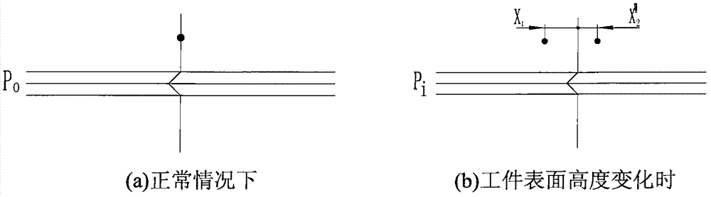
[0056] Figure 4 It is a point-line combined seam tracking system of two point lasers shown according to the embodiment, which is combined with figure 1 The difference is that the visual sensing device includes two point lasers 3; the two point lasers 3 are respectively installed on the left and right sides of the first adjustment frame 2, and can slide along the first adjustment frame 2 (Y direction). Two point-shaped lasers 3 are irradiated vertically downward on the surface of the workpiece, and the two laser points are respectively located on the left and right sides of the weld;
[0057] The angle β between the axis of the linear laser 7 and the vertical direction is 45°; the distance between the first adjustment frame 2 and the area array camera 4 is 12 mm; the laser points emitted by the two point lasers 3 are respectively projected on both sides of the weld 11 At a distance of 10 mm, ensure that the laser point on the workpiece 10 coincides with the laser line, and is...
Embodiment 3
[0060] Figure 5 It is a schematic diagram of the point-line laser combined seam tracking system for welding non-standard circular cross-section workpieces according to the embodiment. The point laser is irradiated vertically on the surface of the workpiece, and the laser point is located on one side of the weld (in the radial direction of the tube section); the line laser 7 is irradiated on the surface of the workpiece obliquely at a certain angle, and the line laser is perpendicular to the weld; the point laser 3. The laser point emitted vertically and the laser line emitted by the linear laser 7 overlap on the workpiece with a non-standard circular section; the area array camera 4 collects the image and transmits it to the computer 5; the distance between the first adjustment frame 2 and the area array camera is 15mm ; The laser point emitted by the point laser 3 is projected on the side of the weld seam at 10 mm. The other method steps are similar to those in Embodiment 1...
PUM
 Abstract
Description
Claims
Application Information
 - R&D Engineer
- R&D Manager
- IP Professional
- Industry Leading Data Capabilities
- Powerful AI technology
- Patent DNA Extraction
Browse by: Latest US Patents, China's latest patents, Technical Efficacy Thesaurus, Application Domain, Technology Topic, Popular Technical Reports.
© 2024 PatSnap. All rights reserved.Legal|Privacy policy|Modern Slavery Act Transparency Statement|Sitemap|About US| Contact US: help@patsnap.com