Fast antenna matching method

A matching method and antenna technology, applied in the directions of antennas, antenna parts, antenna supports/installation devices, etc., can solve problems such as unintuitiveness, complicated calculation process, affecting design efficiency, etc., and achieve fast matching work and save machine costs. Effect

Inactive Publication Date: 2017-07-25
GUANGZHOU YOUCAIHUA INFORMATION TECH CO LTD
View PDF3 Cites 8 Cited by
  • Summary
  • Abstract
  • Description
  • Claims
  • Application Information

AI Technical Summary

Problems solved by technology

Existing 13.56MHz card reader chips usually provide reference circuits and matching component values, and then calculate antenna matching values ​​through theoretical formulas, but the calculation process of this method is complicated and unintuitive, which affects design efficiency

Method used


Image

  • Fast antenna matching method
  • Fast antenna matching method
  • Fast antenna matching method

Examples


Embodiment

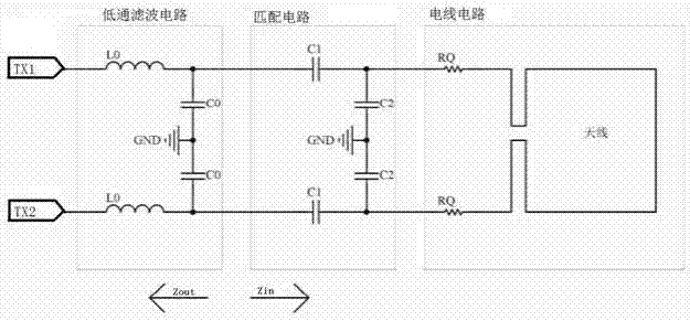
[0056] Such as figure 2 As shown, a general design circuit for a 13.56MHz antenna includes a low-pass filter circuit, a matching circuit, and an antenna circuit.

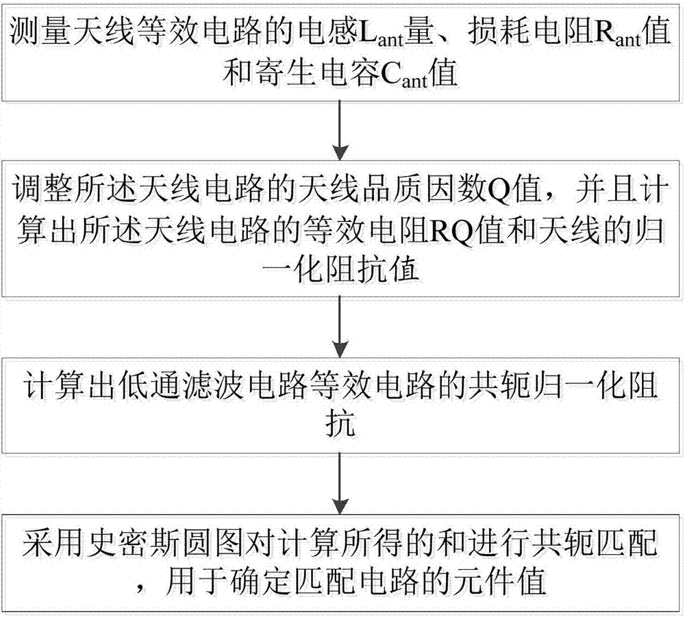
[0057] Such as figure 1As shown, a fast antenna matching method includes the following steps:

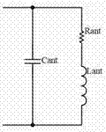
[0058] Step S1, measuring the inductance Lant value, the loss resistance Rant value and the parasitic capacitance Cant value of the antenna equivalent circuit;

[0059] Step S2, adjust the antenna quality factor Q value of the antenna circuit, and calculate the series resistance RQ value of the adjusted Q value of the antenna circuit and the normalized impedance of the antenna circuit value;

[0060] Step S3, calculating the conjugate normalized impedance of the equivalent circuit of the low-pass filter circuit

[0061] Step S4, use the Smith chart to calculate the obtained and Conjugate matching is used to determine the component values ​​of the matching circuit.

[0062] Said step S1 comprises the following...


PUM


Abstract

The invention relates to a wireless communication technology, and particularly discloses a fast antenna matching method. The method comprises the following steps: step S1, measuring inductance Lant amount, a loss resistance Rant value and a parasitic capacitance Cant value of an antenna equivalent circuit; step S2, adjusting the antenna quality factor Q of the antenna circuit, calculating a series resistance RQ value of the adjustment Q value of the antenna circuit and a normalized impedance (the formula is as shown in the specification) value of the antenna circuit; step S3, calculating conjugate normalized impedance (the formula is as shown in the specification) of an equivalent circuit of a low pass filter circuit, and step S4, adopting a smith chart to perform conjugate match on the calculated (the formula is as shown in the specification) and (the formula is as shown in the specification). According to the fast antenna matching method disclosed by the invention, an antenna circuit test process is processed by using the smith chart and a corresponding matching calculation flow, therefore no network analyzer is needed in the test process, and the matching work can be accomplished just by using one LCR electronic tester, thereby reducing the machine cost, and ensuring faster, simpler and more visual and understandable matching work.

Description

technical field [0001] The invention relates to wireless communication technology, in particular to a fast antenna matching method. Background technique [0002] Radio Frequency Identification (RFID) is a non-contact automatic identification technology. It conducts non-contact two-way data communication through radio frequency to identify targets and obtain relevant data. It has the advantages of low cost and high positioning accuracy. . The antenna is an important part of the RFID system, which restricts the development of RFID technology in many scenarios, so the research and design of the RFID antenna is very urgent. 13.56MHz wireless smart cards have been widely used, such as bus IC cards, second-generation ID cards and other applications, and the protocols followed are ISO / IEC 14443-Type A and ISO / IEC 14443-Type B. Existing 13.56MHz card reader chips usually provide reference circuits and matching component values, and then calculate antenna matching values ​​through ...

Claims


Application Information

Patent Timeline
Patent Type & Authority Applications(China)
IPC IPC(8): H04B1/401H01Q1/22H01Q23/00
CPCH04B1/401H01Q1/2208H01Q23/00
Inventor 杨光黄坚鸣
Owner GUANGZHOU YOUCAIHUA INFORMATION TECH CO LTD
Why Eureka
Try Eureka