A tinning device for gear-lifting bus bar joints

A busbar connector and lift-type technology is applied in the field of gear-lifting copper busbar connector tinning devices, which can solve the problems of unstable tinning surface treatment effect, outstanding safety problems of tinning surface, easy to burn the human body, etc. Good effect, low production cost, good for promotion

Active Publication Date: 2019-02-15
STATE GRID ZHEJIANG ELECTRIC POWER +1
View PDF9 Cites 0 Cited by
  • Summary
  • Abstract
  • Description
  • Claims
  • Application Information

AI Technical Summary

Problems solved by technology

[0006] 1) Timeliness issue
[0007] ①The effect of tinning surface treatment is not stable, and it is often necessary to repeat tinning or use fitter technology for leveling treatment, which is inefficient (taking a set of three copper bar joints as an example, it takes about 35 minutes to 50 minutes; ②Many personnel are redundant (three operators, one full-time guardian), it will cause manpower tension
[0008] 2) Security issues
[0009] ①Splash of high-temperature tin water during operation can easily burn the human body; ②Oxyacetylene flame melts tin to form a local high temperature, and the high-temperature movement of the open flame can easily burn the human body
The safety problem of using traditional methods to deal with the tin-coated surface is prominent

Method used


Image

  • A tinning device for gear-lifting bus bar joints
  • A tinning device for gear-lifting bus bar joints
  • A tinning device for gear-lifting bus bar joints

Examples


Embodiment 1

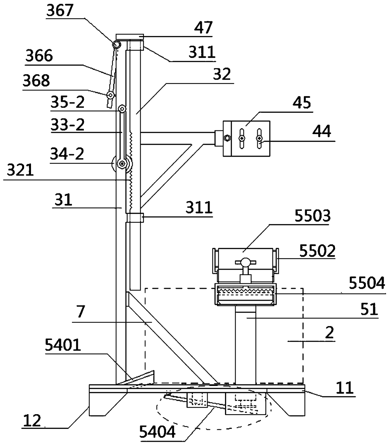
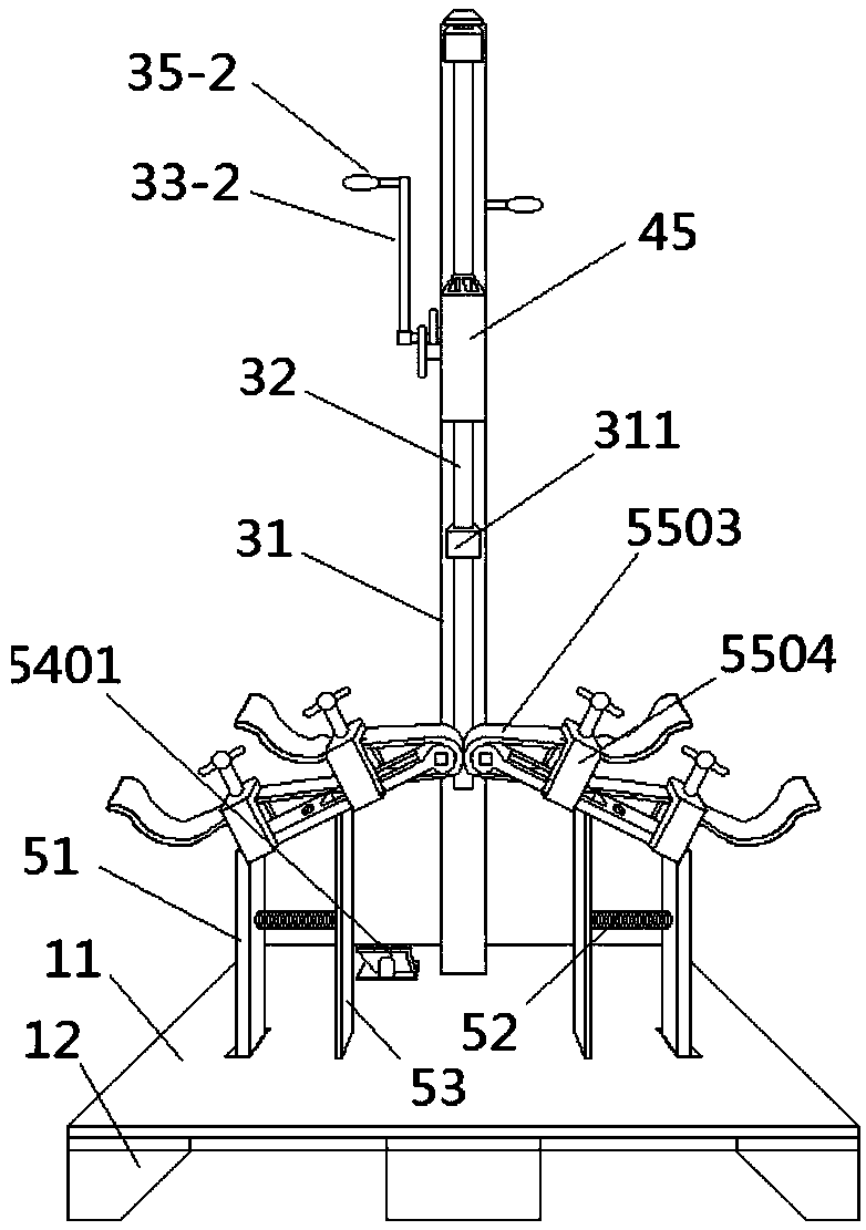
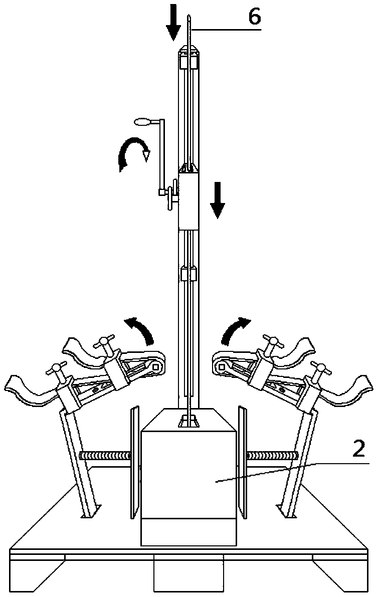
[0072] Such as Figure 1-4 As shown, a gear lifting type copper bar bus joint tinning device includes a base, a tin melting mechanism 2, a gear type copper bar lifting mechanism, a copper bar fixing mechanism and a copper bar wiping mechanism.

[0073] The base includes a base plate 11 and feet 12 provided at the bottom of the base plate.

[0074] Such as figure 1 As shown, the gear-type copper bar lifting mechanism includes a main load-bearing column 31, a lift-type main support frame 32 and a gear-type lifting adjustment mechanism; the main load-bearing column is erected on the base plate, and the main load-bearing column is connected to the base plate. There are reinforcing ribs 7 . The gear-type lifting adjustment mechanism is installed on the main load-bearing column, and it includes a lifting handle 33-2, a hand handle coaxial pinion 34-2 and a hand handle handle 35-2. The lifting hand crank and the coaxial pinion of the hand crank are coaxially installed on the main ...

Embodiment 2

[0082] Such as Figure 11 As shown, a gear lifting type copper bar bus joint tinning device includes a base, a tin melting mechanism 2, a gear type copper bar lifting mechanism, a copper bar fixing mechanism and a copper bar wiping mechanism.

[0083] The difference between this embodiment and embodiment 1 is:

[0084] (1) Gear type lifting adjustment mechanism: such as figure 1 , Figure 14-16 As shown, the gear-type lifting adjustment mechanism includes a lifting wheel 33-1, a wheel coaxial pinion 34-1 and a lifting wheel handle 35-1. The lifting wheel and the coaxial pinion of the wheel are coaxially installed on the main load-bearing column, and the lifting wheel and the coaxial pinion of the wheel are coaxially rotated synchronously, and the coaxial pinion of the wheel meshes with the rack. The lift wheel handle is fixed on the lift wheel. The ratio of the radius of the lifting wheel to the radius of the wheel coaxial pinion is 4:1.

[0085] (2) The positioning metho...

Embodiment 3

[0087] Such as Figure 17 As shown, a gear lifting type copper bar bus joint tinning device includes a base, a tin melting mechanism 2, a gear type copper bar lifting mechanism, a copper bar fixing mechanism and a copper bar wiping mechanism.

[0088] The difference between this embodiment and embodiment 1 is:

[0089] (1) Gear type lifting adjustment mechanism: such as Figure 17 As shown, the gear-type lifting adjustment mechanism includes a lifting wheel 33-1, a wheel coaxial pinion 34-1 and a lifting wheel handle 35-1. The lifting wheel and the coaxial pinion of the wheel are coaxially installed on the main load-bearing column, and the lifting wheel and the coaxial pinion of the wheel are coaxially rotated synchronously, and the coaxial pinion of the wheel meshes with the rack. The lift wheel handle is fixed on the lift wheel. The ratio of the radius of the lifting wheel to the radius of the wheel coaxial pinion is 6:1.

[0090] (2) The positioning method of the liftin...


PUM


Abstract

The invention relates to the field of electric machining equipment, and discloses a gear lifting copper bar busbar joint tin enameling device. The device comprises a base, a tin melting mechanism, a gear copper bar lifting mechanism, a copper bar fixing mechanism and a copper bar wiping mechanism; the gear copper bar lifting mechanism includes a main bearing column, a lifting main support frame and a gear lifting adjusting mechanism; the main bearing column is vertically arranged on the base; the gear lifting adjusting mechanism is mounted on the main bearing column; the main bearing column is provided with a clamping groove; the lifting main support frame is vertically fixed in the clamping groove; the copper bar fixing mechanism is fixed on the lifting main support frame; the tin melting mechanism is arranged on the base; and the copper bar wiping mechanism includes a stepped transmission part, and two sets of wiping parts, wiping parts support frames, return springs and wiping part positioning plates arranged in a mirror image manner. The device can realize semi-automatic tin enameling of copper bar busbar joints, is high in working efficiency, excellent in tin enameling effect, high in safety and low in manufacturing cost, and facilitates popularization.

Description

technical field [0001] The invention relates to the field of electrical processing equipment, in particular to a tinning device for a gear lifting type copper bar bus joint. Background technique [0002] During the maintenance, renovation and installation of power substation professional equipment, it is often necessary to make conductive copper bar joints. In this work, there is a very critical process that needs to be completed: copper busbar joint tinning. The significance of tin enamel lies in that the tin enamel of the copper bar connector can effectively prevent the oxidation and electrochemical corrosion of the overlapping surface of the copper bus bar, and avoid the increase of contact resistance. The requirements for lap joints of copper busbars are clearly stipulated in the national standard of the People's Republic of China "Code for Construction and Acceptance of Busbar Devices in Electrical Installation Engineering" (GB / 50149-2010), Section 3.1.8 of GB / 50149-...

Claims


Application Information

Patent Timeline
Patent Type & Authority Patents(China)
IPC IPC(8): B23K3/00
CPCB23K3/00
Inventor 陈海伟陈顶灵倪建华林传葛陈传音蒋正浩董士幼
Owner STATE GRID ZHEJIANG ELECTRIC POWER
Why Eureka
Try Eureka