
Method for taking out die pouring gate buffering pit movable materials

A mold and live material technology, which is applied in the field of casting mold making, can solve the problems of material loss, easily damaged sand core, time waste, etc., and achieve the effects of improving efficiency, reducing costs, and convenient operation

Inactive Publication Date: 2017-07-25
NINGXIA KOCEL MOLD
View PDF5 Cites 5 Cited by
  • Summary
  • Abstract
  • Description
  • Claims
  • Application Information

AI Technical Summary

Problems solved by technology

[0002] At present, the loose material of the mold sprue buffer nest is taken out by using the live material to leave a hole, and a small iron rod is used to take it out by hand. Since the size of the sprue is often small and cannot be reached by hand, it is very difficult to take out the live material, and it is very dependent on the operator. experience, and it is easy to damage the sand core, and it is necessary to repair the sand core again, resulting in a waste of time and material loss, and has a great impact on the quality of the sand core, which greatly reduces the efficiency of making sand cores;
[0003] With the continuous improvement of sand core quality requirements, the requirements for production efficiency are getting higher and higher. The current method of taking out live materials is becoming more and more difficult to adapt to the current high-efficiency working conditions. Therefore, it is necessary to improve the method of taking out runner buffer nest live materials , reducing the loss of manpower and materials is very important to improve the efficiency of sand core production

Method used


Image

  • Method for taking out die pouring gate buffering pit movable materials

Examples


Embodiment Construction

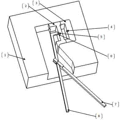
[0015] In order to enable those skilled in the art to better understand the technical solution of the present invention, the following in conjunction with the attached figure 1 The present invention is further analyzed.

[0016] like figure 1 Shown, a kind of method for taking out mold sprue buffer nest live material, comprises the following steps:

[0017] Step 1: Using the principle of leverage, the tooling support rod 7 and the tooling rotating rod 8 are produced, and a magnet is fixed at one end of the tooling rotating rod 8; the tooling rotating rod 8 and the tooling supporting rod 7 are connected by a rotatable shaft;

[0018] Step 2. When designing each live material, the live material is designed to be hollow, and a magnet is fixed in the middle of the live material in advance, and the magnetic poles are calculated; the live material is one or more;

[0019] Step 3, when taking the loose piece, extend the end of the rotating rod with the magnet into the cavity, so th...


PUM


Abstract

The invention relates to a method for taking out die pouring gate buffering pit movable materials. The method includes the steps that firstly, a level principle is adopted, a tool supporting rod and a tool rotating rod are manufactured, a magnet is fixed to one end of the tool rotating rod, and the tool rotating rod and the tool supporting rod can be connected through a rotatable shaft; secondly, hollow design is adopted in the movable materials when the movable materials are designed, a magnet is fixed to the middle of each movable material in advance, and the magnetic pole is calculated; thirdly, when the movable materials are taken, the end, with the magnet, of the rotating rod stretches in a cavity, the magnet of the rotating rod and the magnet of the movable material I are attracted to each other, then the rotating rod is slowly rotated, and the movable material is dragged out; and fourthly, the movable material I and the movable material II are connected through a locating pin, when the movable material I is taken out through the tool, the movable material II can be driven to move to the previous position of the movable material I, the movable material I is downwards taken out at the moment, the movable material II can be reserved in the previous position of the movable material I, and the movable material II is taken out through the same method. The method has the beneficial effects that the efficiency is improved, the cost is reduced, and operation is convenient.

Description

technical field [0001] The invention relates to a method for taking out the live material of the deep cavity of the mold runner, in particular to a method for taking out the live material of the buffer nest of the mold runner, and belongs to the field of casting mold making. Background technique [0002] At present, the loose material of the mold sprue buffer nest is taken out by using the live material to leave a hole, and a small iron rod is used to take it out by hand. Because the size of the sprue is often too small to reach in, it is very difficult to take out the live material, and it is very dependent on the operator. experience, and it is very easy to damage the sand core, and it is necessary to repair the sand core again, resulting in a waste of time and material loss, and has a great impact on the quality of the sand core, which greatly reduces the efficiency of making sand cores; [0003] With the continuous improvement of sand core quality requirements, the requi...

Claims


Application Information

Patent Timeline
Patent Type & Authority Applications(China)
IPC IPC(8): B22C9/10B22C9/08
CPCB22C9/10B22C9/082
Inventor 顾阳
Owner NINGXIA KOCEL MOLD
Learn More