
Special high-efficiency stirrer for conductive slurry

A technology of conductive paste and mixer, which is applied to mixers with rotating stirring devices, mixers, dissolution, etc., which can solve the problems of aggregate deposition, electrical conductivity, field emission performance degradation, and inability to disperse large aggregates. , to achieve the effect of improving the efficiency of breaking up, improving the efficiency of use, and increasing the cutting area

Inactive Publication Date: 2017-07-25
江苏昱星科技股份有限公司
View PDF0 Cites 12 Cited by
  • Summary
  • Abstract
  • Description
  • Claims
  • Application Information

AI Technical Summary

Problems solved by technology

[0002] As an important part of battery production, conductive paste needs to be mixed with various raw materials. During the mixing process, semi-finished paste tends to have large aggregates. It is necessary to break up the large aggregates in time and separate the paste. Stir the material evenly, otherwise it will easily lead to a series of performance reductions such as electrical conductivity and field emission performance
Most of the mixing equipment currently used is stirred by outsourced reactors or dispersing machines. Most of the common reactors or dispersing machines use a single or multiple vertical stirring rod structure, and the stirring rods are rotated inside the machine for stirring. Although it can achieve a certain stirring effect and mix the liquid slurry, it cannot break up the large aggregates in a targeted manner, and the stirring effect is often poor, and it is difficult to meet the quality requirements of the conductive paste.
[0003] And during the stirring process of the conductive paste, the technicians found that it is difficult to touch the paste at the bottom of the body due to the ordinary stirring rod stirring inside the body, so the bottom of the body is prone to aggregate deposition, which is not conducive to the uniform stirring of the conductive paste

Method used


Image

  • Special high-efficiency stirrer for conductive slurry
  • Special high-efficiency stirrer for conductive slurry
  • Special high-efficiency stirrer for conductive slurry

Examples


Embodiment

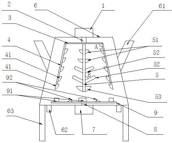
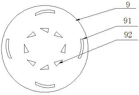
[0026] A special high-efficiency mixer for conductive paste, comprising a mixer shell, wherein the mixer shell has a round truncated cone structure with a narrow top and a wide bottom. The interior of the mixer shell is a hollow structure, and both sides of the mixer shell are provided There is a feed inlet, supporting feet are provided on both sides of the bottom of the mixer shell, and a discharge port is provided at both ends of the bottom of the mixer shell; a first motor is arranged at the center of the top of the mixer shell, and The center of the bottom of the mixer shell is provided with a second motor; the inside of the mixer shell is provided with a first motor shaft, a horizontal stirring rod, an oblique stirring rod, a vertical stirring rod, a second motor shaft and a bottom rotating disk,

[0027] The top of the first motor shaft is connected to the first motor, and the bottom is extended into the inside of the mixer shell to weld the horizontal stirring rod, the firs...


PUM


Abstract

A special high-efficiency stirrer for conductive slurry is characterized in that a first motor is arranged in the center of the top of a stirrer shell, and a second motor is arranged in the center of the bottom of the stirrer shell; and a first motor shaft, a transverse stirring rod, tilting stirring rods, a vertical stirring rod, a second motor shaft and a bottom rotating disc are arranged in the stirrer shell. The design of multiple stirring rods is adopted to improve the multi-angle stirring efficiency, various blades are cooperated to effectively scatter large agglomerates in the slurry from all angles, and the bottom rotating disc is especially arranged to effectively prevent the deposition phenomenon in the stirrer body, so the use efficiency is improved.

Description

Technical field [0001] The invention relates to a high-efficiency mixer special for conductive paste. Background technique [0002] As an important part of battery production, conductive paste needs to mix a variety of raw materials during its preparation. During the mixing process, the semi-finished paste is prone to have large agglomerates, and the large agglomerates need to be broken up in time. Stir the material uniformly, otherwise it will easily lead to a series of performance degradations such as conductivity and field emission performance. Most of the currently used stirring equipment uses purchased reactors or dispersers for stirring. Common reactors or dispersers mostly use a single or multiple vertical stirring rod structure, and the stirring rod rotates inside the machine for stirring. Although it can achieve a certain stirring effect and mix the liquid slurry, it cannot break up large agglomerates in a targeted manner. The stirring effect is often poor and it is dif...

Claims


Application Information

Patent Timeline
IPC IPC(8): B01F7/16
CPCB01F27/074B01F27/172B01F27/192B01F27/85
Inventor 陈春锦王卿
Owner 江苏昱星科技股份有限公司
Learn More