Cooking device

A cooking device and installation cavity technology, which is applied to kitchen utensils, home utensils, roasters/barbecue grids, etc., can solve the problems of troublesome replacement process, microwave leakage, and long time-consuming maintenance work, and achieves simple operation and elimination of maintenance. Safety hazards and the effect of improving satisfaction

Pending Publication Date: 2017-07-25
GUANGDONG MIDEA KITCHEN APPLIANCES MFG CO LTD +1
View PDF7 Cites 2 Cited by
  • Summary
  • Abstract
  • Description
  • Claims
  • Application Information

AI Technical Summary

Problems solved by technology

The cooking device includes a base and a furnace door hinged to the base. The lower surface of the furnace door is provided with a chamber for containing the food to be cooked. The furnace door can be rotated up and down relative to the base to open or close the chamber. Install the installation cavity of the heating tube. The top of the installation cavity needs to be installed with a loading plate for supporting the food to be heated. A magnetron is also installed in the base of the cooking device. The microwave emitted by the magnetron passes through the loading plate to heat the food with microwaves. Therefore, the loading plate must be made of non-microwave shielding material, such as glass. At the same time, in order to prevent microwave leakage, the loading plate and the top plate of the base must be hermetically connected. The carrier board is fragile and is prone to breakage when the product is in use. Therefore, when the carrier board is damaged, it is necessary to remove the silica gel connecting the carrier board and the top plate of the base to remove the broken carrier board and use silica gel It is very troublesome to re-seal and fix the new carrier plate on the top plate of the base, and the maintenance work takes a long time, resulting in a decline in customer satisfaction. Moreover, replacing the carrier plate is also likely to cause microwave leakage due to insufficient sealing. There are security risks

Method used


Image

  • Cooking device
  • Cooking device
  • Cooking device

Examples


Embodiment Construction

[0032] In order to understand the above-mentioned purpose, features and advantages of the present invention more clearly, the present invention will be further described in detail below in conjunction with the accompanying drawings and specific embodiments. It should be noted that, in the case of no conflict, the embodiments of the present application and the features in the embodiments can be combined with each other.

[0033] In the following description, many specific details are set forth in order to fully understand the present invention. However, the present invention can also be implemented in other ways than described here. Therefore, the protection scope of the present invention is not limited by the specific implementation disclosed below. Example limitations.

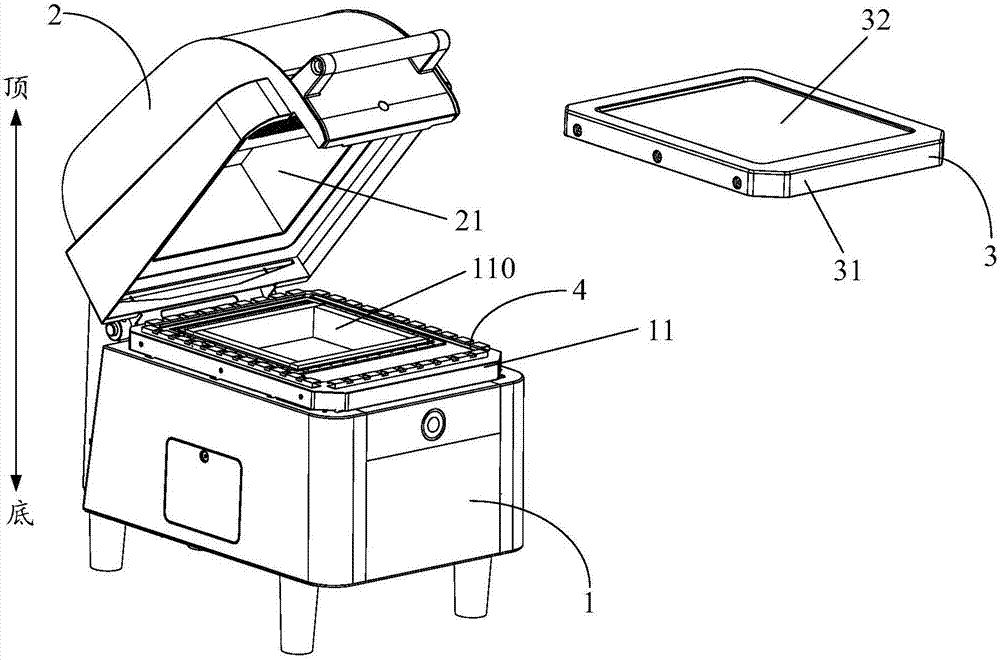
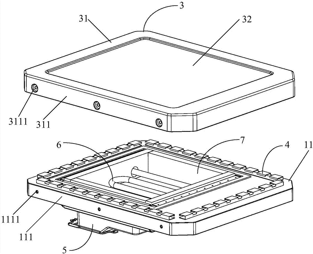
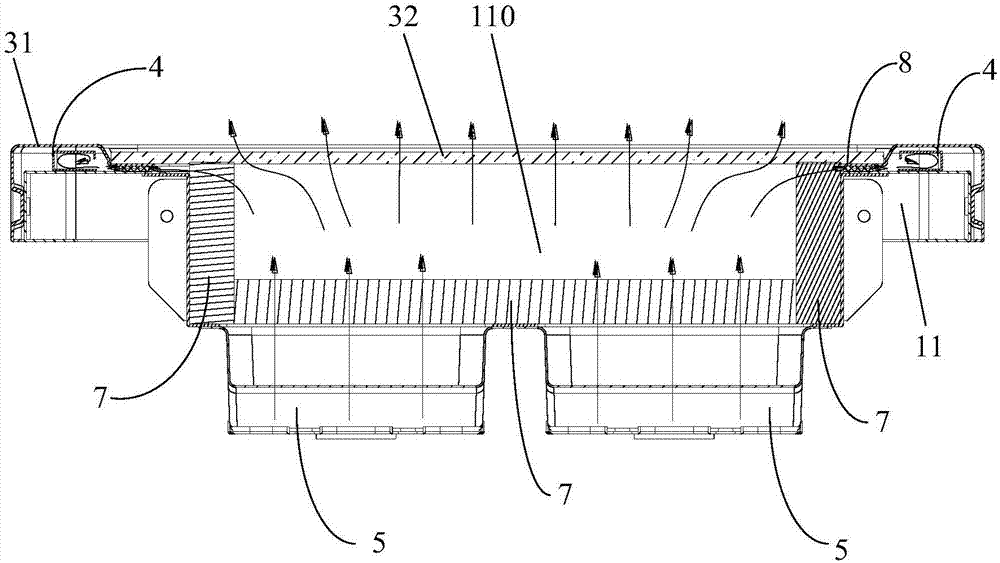
[0034] Such as Figure 1 to Figure 5 As shown, the embodiment of the present invention provides a cooking device, including a base 1 and a furnace door 2 hinged with the base 1, the lower surface of the furn...


PUM


Abstract

The invention provides a cooking device. The cooking device comprises a base and a furnace door hinged to the base, and further comprises a cooking platform and a microwave shielding piece, the cooking platform comprises a border and an object loading plate installed on the border, the object loading plate is made from a non-microwave shielding material, the border is detachably installed on a top plate of the base, an abutting support surface is formed between the lower surface of the border and the upper surface of the top plate, the bottom of the top plate is provided with a magnetron, the magnetron is used for transmitting microwaves to the object loading plate from the inner side of the support surface, and the microwave shielding piece is installed on the top plate, is surrounded at the outer side of the support surface, and is used for shielding microwaves leaked from the position of the support surface. In the cooking device, the object loading plate and the top plate of the base adopt separated type design, the object loading plate is detachably installed on the top plate of the base through the border, so that the object loading plate is convenient to replace, moreover, the top plate of the base is provided with the microwave shielding piece, and the microwave shielding piece is surrounded at the outer side of the support surface between the border and the top plate of the base to prevent microwave leakage.

Description

technical field [0001] The present invention relates to the field of kitchen appliances, more specifically, to a cooking device. Background technique [0002] With the development of the times, the types of cooking devices have become more and more diverse. At present, a new type of barbecue cooking device has appeared on the market, and the cooking device can be used to heat Panini food and sandwiches. The cooking device includes a base and a furnace door hinged to the base. The lower surface of the furnace door is provided with a chamber for containing the food to be cooked. The furnace door can be rotated up and down relative to the base to open or close the chamber. Install the installation cavity of the heating tube. The top of the installation cavity needs to be installed with a loading plate for supporting the food to be heated. A magnetron is also installed in the base of the cooking device. The microwave emitted by the magnetron passes through the loading plate to h...

Claims


Application Information

Patent Timeline
IPC IPC(8): A47J37/06A47J37/01
CPCA47J37/01A47J37/0623A47J37/0664Y02B40/00
Inventor 安明波凌奇宏
Owner GUANGDONG MIDEA KITCHEN APPLIANCES MFG CO LTD
Why Eureka
Try Eureka