Concrete hidden-crack detection method and system based on contact-type ultrasonic waves
A technology for crack detection and concrete, which is applied to the analysis of solids using sound waves/ultrasonic waves/infrasonic waves, material analysis using sound waves/ultrasonic waves/infrasonic waves, and measuring devices. It can solve problems such as low sound energy efficiency and insufficient accuracy of detection results. , to achieve the effect of increasing the sound energy input rate
- Summary
- Abstract
- Description
- Claims
- Application Information
AI Technical Summary
Problems solved by technology
Method used
Image
Examples
Embodiment approach
[0031] This embodiment specifies the implementation of the method of this method, which specifically includes the following steps:
[0032] 1) Using contact ultrasonic excitation, a copper sheet is used as a coupling between the ultrasonic excitation head and the surface of the concrete component to be tested, and the ultrasonic wave is input into the concrete component to be tested to excite it; the thickness of the copper sheet is 0.5-1mm; The sheet is placed as a gasket between the concrete member and the contact surface of the ultrasonic excitation head (the structure of the copper sheet is as follows image 3 shown), or cover the excitation head with copper sheet (such as Figure 8 shown), forming an integral structure with the excitation head;
[0033] 2) Obtain a thermal image of the concrete component under test by using an infrared thermal imager;
[0034] 3) Determine the position of the crack in the concrete member according to the local high-temperature position ...
Embodiment 2
[0050] This embodiment specifically illustrates the implementation of the system of this invention, specifically as follows:
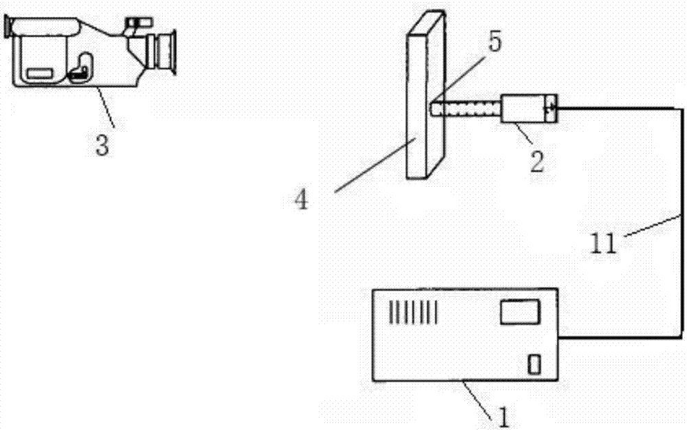
[0051] Such as figure 1 As shown, a concrete hidden crack detection system based on contact ultrasonic waves includes an ultrasonic source 1, an ultrasonic excitation head 2 and an infrared thermal imager 3. The ultrasonic source 1 is connected to the ultrasonic excitation head 2 through a cable 11. The ultrasonic The excitation head 2 is in contact with the concrete component 4 to be tested for ultrasonic excitation. The infrared thermal imager 3 is used to monitor the thermal image of the concrete component 4 to be tested. The contact surface of the ultrasonic excitation head 1 and the concrete component 4 to be tested is There is a copper sheet 5 as a coupling.
[0052] Refer to Example 1 for optimal parameter settings of ultrasonic excitation.
[0053] The ultrasonic excitation head is selected from an ultrasonic spot welding gun or an ultrasonic v...
PUM
| Property | Measurement | Unit |
|---|---|---|
| thickness | aaaaa | aaaaa |
Abstract
Description
Claims
Application Information
 - Generate Ideas
- Intellectual Property
- Life Sciences
- Materials
- Tech Scout
- Unparalleled Data Quality
- Higher Quality Content
- 60% Fewer Hallucinations
Browse by: Latest US Patents, China's latest patents, Technical Efficacy Thesaurus, Application Domain, Technology Topic, Popular Technical Reports.
© 2025 PatSnap. All rights reserved.Legal|Privacy policy|Modern Slavery Act Transparency Statement|Sitemap|About US| Contact US: help@patsnap.com


