
A split channel type pumping station regulating pool

A technology of regulating tanks and diverter tanks, which is applied in the configuration of pumping stations, water supply tanks, buildings, etc., can solve the problems of large hydraulic loss at the turning, large water surface drop at the head and tail of the regulating tank, and low space utilization. Achieve the effect of reducing local hydraulic loss, facilitating uniform inflow, and reducing unstable vibration

Inactive Publication Date: 2019-03-05
HOHAI UNIV
View PDF3 Cites 0 Cited by
  • Summary
  • Abstract
  • Description
  • Claims
  • Application Information

AI Technical Summary

Problems solved by technology

[0003] At present, in the regulating pool of the pumping station, the regulating pool in the form of a groove is used to prevent sedimentation by water flow, that is, the regulating pool is designed as a strip-shaped groove, and the bottom of the groove is designed as a semi-arc shape. By increasing the flow rate at the bottom of the groove To enhance the sand-carrying capacity of the water flow at the bottom of the regulating pool, this type of regulating pool has a large flow rate per unit width, a large local hydraulic loss at the turning, a relatively long flow process, and a large hydraulic loss along the way. The head of the regulating pool and The drop in the water surface at the tail is relatively large, and the space utilization rate is relatively low, which may affect the regulation and storage capacity of the regulating tank of the pumping station

Method used


Image

  • A split channel type pumping station regulating pool
  • A split channel type pumping station regulating pool
  • A split channel type pumping station regulating pool

Examples


Embodiment 1

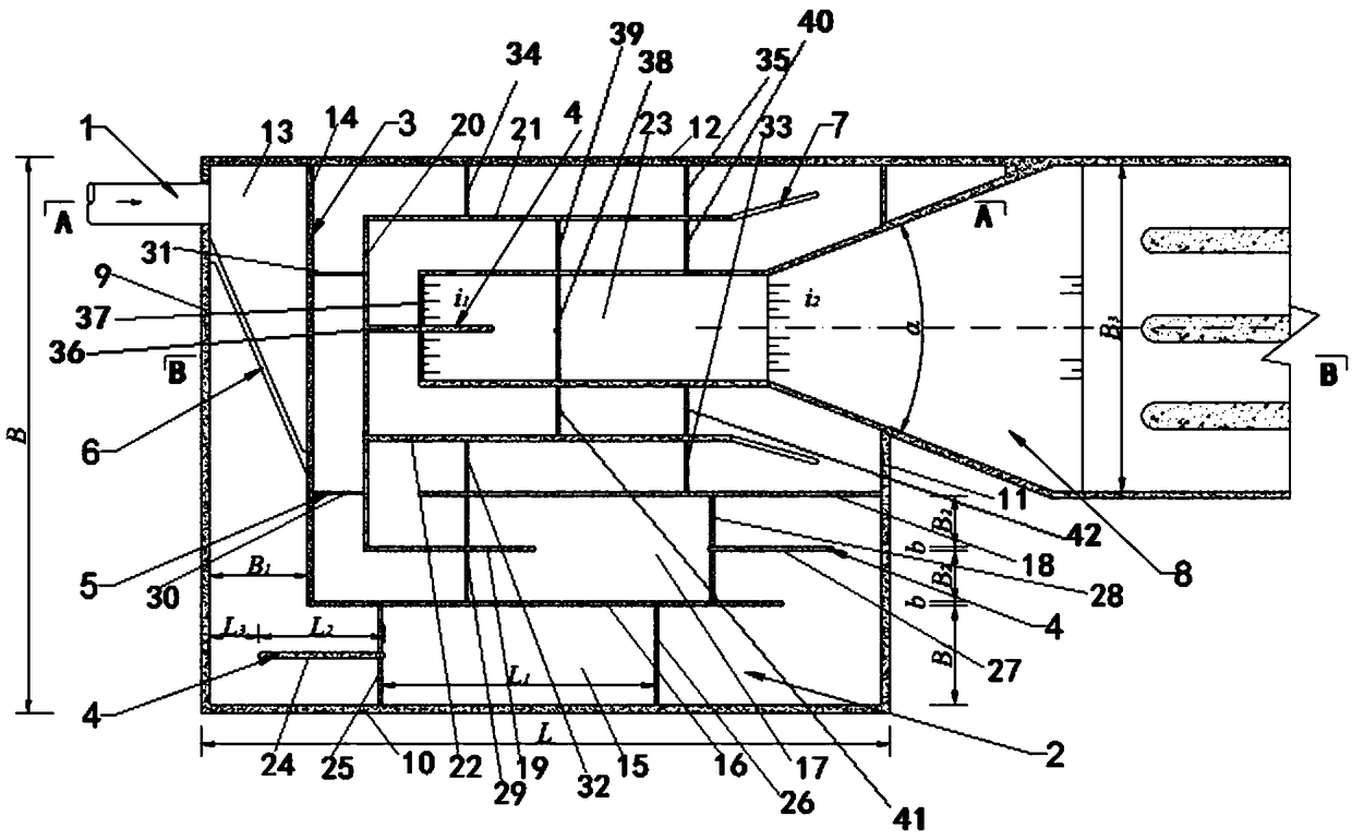
[0036] Such as Figure 1 ~ Figure 4 As shown, a shunt channel type pumping station regulating tank includes a regulating tank with a rectangular outer contour. 8 connected, the inside of the regulating pool is separated by a partition wall 3 into a circuitous flow tank 2 connecting the water inlet and the water outlet, and the flow tank 2 is provided with a deflector 4 for diverting flow and a vertical partition for adjusting the flow rate 5.

[0037] The launder 2 includes several transverse launders and longitudinal launders; the side wall of the regulating tank is surrounded by the left side wall 9, the front side wall 10, the right side wall 11 and the rear side wall 12, and the water inlet pipe 1 is located at On the left side wall 9 and close to the rear side wall 12, the water inlet pipe 1 communicates with the first transverse flow groove 13, and the first transverse flow groove 13 is formed by the left side wall 9 and the left side wall. The first partition wall 14 ...

Embodiment 2

[0051] The difference between this embodiment and embodiment 1 is only: B 2 =0.6B 1 , h=H,L 1 =7h,L 2 = 1.5B 1 .

Embodiment 3

[0053] The difference between this embodiment and embodiment 1 is only: B 2 =0.4B 1 , h=0.8H, L 1 =6h,L 2 =B 1 .


PUM


Abstract

The invention discloses a distribution groove channel type pump station regulating pool. The regulating pool comprises a regulating pool body of which the outer outline is rectangular, the water inlet end of the regulating pool body is connected with a water inlet pipe (1), the water outlet of the regulating pool body is connected with a pump station front pool (8), a roundabout type flow groove (2) which is communicated with the water inlet end and the water outlet end is formed in the regulating pool body by the partition of a partition wall (3), and a diversion plate (4) for distribution and a vertical partition plate (5) for adjusting a flow velocity are arranged in the flow groove (2). According to the distribution groove channel type pump station regulating pool, on one hand, groove channel distribution is adopted, the turning radius of water flow at a 90-degree bend and the turning radius of the water flow at a 180-degree bend are reduced, the partial hydraulic loss when the water flow turns is reduced, and the flow velocity distribution in the flow groove is uniform; one the other hand, through the additional arrangement of the flow guide plate and the vertical partition plate, the flow distribution and flow velocity distribution when the water flow turns are improved, the water flow velocity at the bottom of the flow groove is increased, and the water flow sediment carrying capacity at a high water level is improved.

Description

technical field [0001] The invention relates to a diversion channel type pumping station regulating tank, in particular to a pumping station regulating tank which prevents sediment deposition by carrying sediment movement with diverting channel water flow, and belongs to the technical field of pumping station engineering of urban water supply and drainage systems . Background technique [0002] In the design of urban pumping stations, in order to adjust the water demand in different regions and at different times, ensure the smooth operation of the pumping station under special working conditions, and adjust the water supply of the pumping station under specific circumstances, the pumping station water intake system is often arranged with adjustment pool. Under normal circumstances, the capacity of the regulating tank of the pumping station is relatively large, and the flow rate of the water flow is relatively low. When the sediment (or suspended solid particles) in the wat...

Claims


Application Information

Patent Timeline
Patent Type & Authority Patents(China)
IPC IPC(8): E03B5/00E03B11/00
CPCE03B5/00E03B11/00
Inventor 王晓升陈毓陵冯建刚周春天张睿佟宏伟朱晓明
Owner HOHAI UNIV
Learn More