Integrated water path structure of water purifier

A technology that integrates waterways and water purifiers. It is used in water/sewage treatment, water/sewage treatment equipment, water/sludge/sewage treatment, etc. It can solve problems such as mutual penetration of waterways, poor product versatility, and unfavorable technology promotion and application. , to achieve the effect of neat and orderly structure, stable and reliable use, and cost reduction

Pending Publication Date: 2017-07-21
DONGGUAN CITY ZHUO YI PLASTIC PROD CO LTD
View PDF7 Cites 1 Cited by
  • Summary
  • Abstract
  • Description
  • Claims
  • Application Information

AI Technical Summary

Problems solved by technology

This structure simplifies the number of joints and standardizes the waterway structure, but there are many new problems: 1. Each waterway module needs to consider its function, installation position, and connection with other modules, so the structure is complicated. It is necessary to separately design a complete set of multiple waterway modules that cooperate with each other. The mold cost alone makes manufacturers of general scale far behind, which is not conducive to the promotion and application of technology; Upgrade the original waterway structure; 3. When this type of integrated waterway has water inside and is in a low temperature environment, the water in the waterway will freeze and expand. Since the integrated waterway is made of hard plastic injection molding, it is easy to cause various The cracks between the waterway modules make the waterways penetrate each other. This kind of situation is more common when it is shipped to a colder area or used in cold weather after the water test before leaving the factory, which seriously affects the quality of the water purifier.

Method used


Image

  • Integrated water path structure of water purifier
  • Integrated water path structure of water purifier
  • Integrated water path structure of water purifier

Examples


Embodiment Construction

[0021] The present invention will be further described below in conjunction with accompanying drawing:

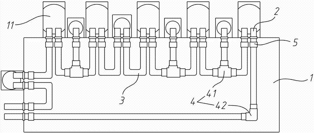
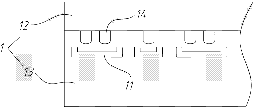
[0022] refer to Figure 1 to Figure 7 The integrated waterway structure of the water purifier shown includes a box-shaped casing 1 , several connectors 2 , and soft water pipes 3 and pipe fittings 4 connecting the connectors 2 . The outer wall of the housing 1 is provided with several mounting brackets 11 for installing the filter element of the water purifier and each control and detection device. The position and quantity of the mounting bracket 11 can be a standard general design. When different numbers of filter elements or different When controlling the detection device, it only needs to be installed on the corresponding installation bracket 11 . The pipe fitting 4 and the soft water pipe 3 are placed in the housing 1, the connector 2 is fixed on the housing 1 and one end protrudes from the housing 1, and the connector 2 protrudes One end of the housing 1 is used to ...


PUM


Abstract

The invention provides an integrated water path structure of a water purifier. The integrated water path structure comprises a shell which is of a box shape in an encircling manner, a plurality of connection heads, and hoses and pipe fittings which are connected with the respective connection heads, wherein the pipe fittings and the hoses are arranged inside the shell; the connection heads are fixed on the shell, and one end of each connection head extends out of the shell; the hoses, the pipe fittings and the connection heads are connected through joint structures; the joint structures comprise hose joints located on the pipe fittings and the connection heads and fastening caps; the front ends of the hose joints are provided with cone steps; the hoses are connected with the cone steps in a tightened sleeving manner; the fastening caps are connected to the peripheries of the hoses in a tightened sleeving manner. The joint structures cannot scratch pipe walls, do not have fatigue damage and are durable and reliable; by the adoption of the closed shell and the cooperation of standard pieces such as the connection heads, the pipe fittings and the hoses, the integrated water path structure is tidy, easy and convenient to mount and firm; no complicated mold is needed; upgrading of different products or functions with the integrated water path structure can be realized only by increasing or decreasing the quantity of the hoses and the quantity of the connection heads, so that the cost is greatly reduced; the hoses cannot be damaged by freezing expansion, so that the integrated water path structure is applicable to environments at various atmospheric temperatures.

Description

technical field [0001] The invention relates to the technical field of water purification equipment components, in particular to an integrated waterway structure of a water purification machine. Background technique [0002] As the technology of water purifiers becomes more and more mature, the quality requirements of water purifiers are getting higher and higher, and the functions are becoming more and more complex. The common RO machine or ultrafiltration machine has more than 4 to 5 different filter elements, in addition to various water quality detection devices and waterway control devices, etc., making the waterway in the water purifier very complicated, and there are many interfaces between the waterways. up to dozens. The traditional method is to use water pipes and joints to connect the waterways, but the joint structure is not reliable. The more common joint structure is the quick-lock joint with metal claws. The plastic elastic claws of this joint will be fatigue...

Claims


Application Information

Patent Timeline
IPC IPC(8): C02F1/00
CPCC02F1/00C02F2201/004C02F2201/002C02F2301/04
Inventor 尹家良
Owner DONGGUAN CITY ZHUO YI PLASTIC PROD CO LTD
Why Eureka
Try Eureka