
Lawn hay mower of brake mechanism, with centrifugal collision beads

A braking mechanism, lawn mower technology, applied in lawn mowers, agricultural machinery and implements, cutters, etc., can solve problems such as increasing safety hazards, insufficient wire length, and large wire area.

Inactive Publication Date: 2017-07-21
NINGBO DAYE GARDEN EQUIP
View PDF4 Cites 0 Cited by
  • Summary
  • Abstract
  • Description
  • Claims
  • Application Information

AI Technical Summary

Problems solved by technology

Anti-collision security and secure braking, mowing and mowing are optional, and there are wires and a large area. These are easier said than done, and they have always been a long-standing problem with electric lawn mowers.
[0007]Why use a cord reel? Because of the long wires scattered on the ground, when the electric lawn mower mows back and forth, sometimes it is accidentally stepped on by feet or crushed by wheels, which affects safety; If the wire is not long enough, mowing is suspended, or the wire is managed manually, which increases safety hazards
Why put a cord reel on an electric lawn mower? Anyone who has used an electric lawn mower knows that weeds often leak when mowing, and they have to be re-mowed. Especially when the environment is complex, such as bushes mixed with the lawn, it is necessary to take several steps forward and several times and repeat the mowing from left to right. Grass; if the reel is placed far away, the wires near the lawn mower cannot be pulled in and out synchronously with the pull and stop in time, or they will fall to the ground limply, and there is a danger of being stepped on or crushed by wheels, or they cannot be pulled in and out in time. Line in and out

Method used


Image

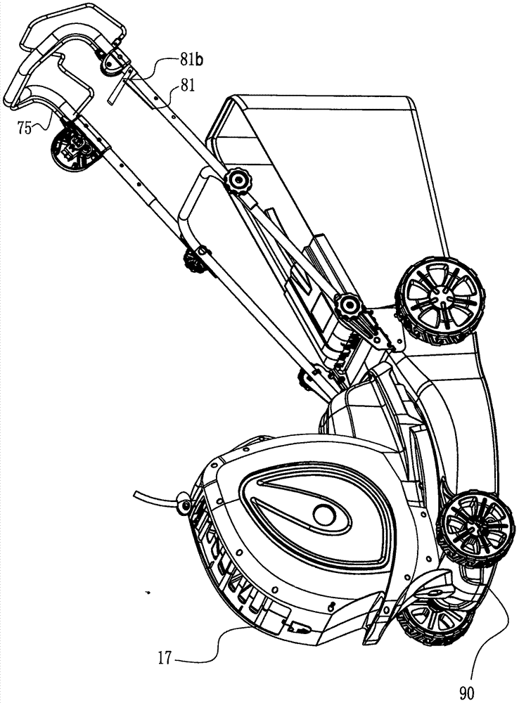
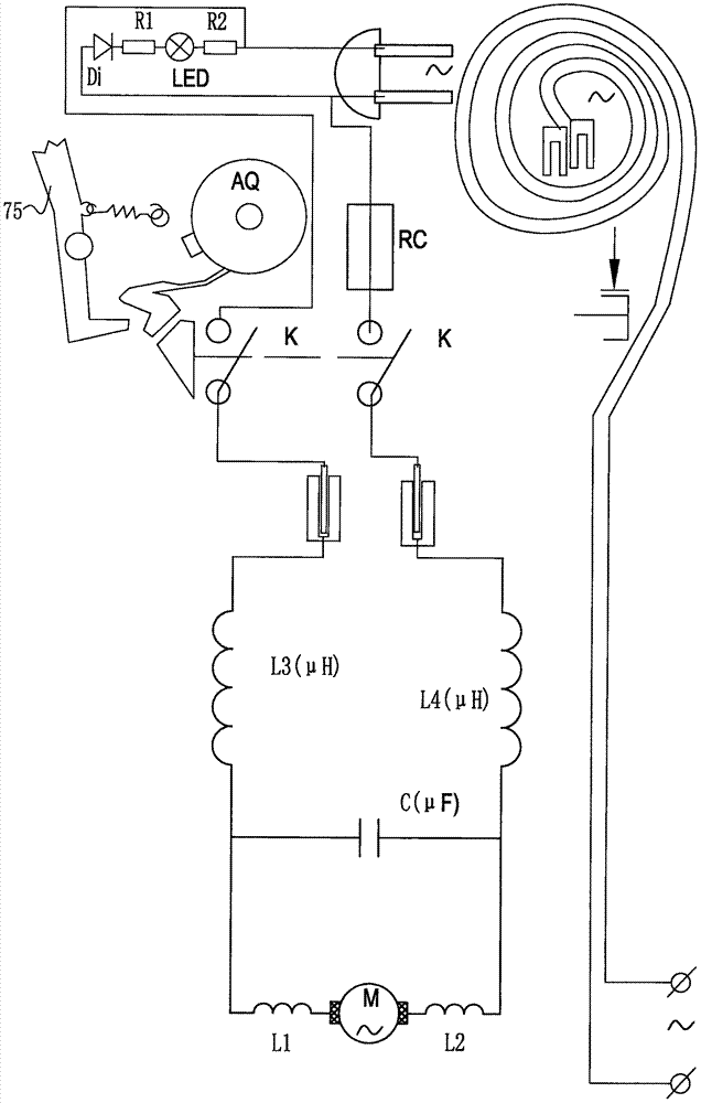
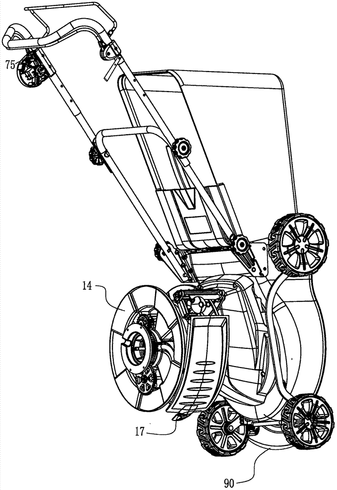
  • Lawn hay mower of brake mechanism, with centrifugal collision beads
  • Lawn hay mower of brake mechanism, with centrifugal collision beads
  • Lawn hay mower of brake mechanism, with centrifugal collision beads

Examples


Embodiment Construction

[0121] Build the computer 3D model first, then engrave the mold; then add anti-collision and brakes to the lawn mower. The technical equation and modeling method are: use PRO / ENGINEER WILDFIRE drawing software, create a new working directory, create new parts, and sketch 2 pieces concentric circles. Open the variable section sweep (Var Sect Sweep) command, select the above 2 circles as the sweep trajectory and the reference trajectory. Draw a straight line parallel to the plane of 2 circles, the length L=(D-d) / 2, and the projection line corresponding to the edge of the circle. Establish parameter (PARAMETER) 1: C is a real number (real number), which can be assigned a value between 0.01-1 according to specific working conditions, such as 0.3; C is also called wave height. Establish parameter (PARAMETER) 2: N integer (integer), select a value between 2-100 according to specific working conditions, such as 13; N is also called wave number. Establish relation (RELATION), be as ...


PUM


Abstract

The invention provides a lawn hay mower of a brake mechanism with centrifugal collision beads. The brake mechanism with the centrifugal collision beads disposed on a belt wheel is composed of multiple groups of centrifugal slide blocks (27), the centrifugal collision beads (28), a centrifugal slide groove (30) and a centrifugal brake plate (29), wherein brake mechanism with the centrifugal collision beads work together with a wave-shaped concave arc (32) on a working clamping disk (31) disposed on an output shaft (203) to conduct positioning and braking; the centrifugal brake plate (29) works together with the output shaft (203) and the working clamping disk (31) for braking; the centrifugal slide block (27) is made of die-casting aluminum; and two pits are formed by pressing on a die-casting aluminum part die at first in the centripetal direction of the centrifugal slide block (27), and then two steel centrifugal beads (28) are put into the pits through pressing. The waveform of the wave-shaped concave arc (32) in the working clamping disk (31) is one section of a logarithmic spiral which is also called as an equiangular spiral and is characterized in that pressure angles are equal at different positions; or the waveform is a section of a cube curve with a buffer collision characteristic. Safety guarantee and braking effects are enhanced, and braking is quick and accurate; and consumption of parts is reduced, and the cost is reduced.

Description

technical field [0001] The invention relates to a lawn mower used for mowing lawns in gardens, parks, roads and other places. The anti-collision safety device at the front of the lawn mower chassis, and the series-excited motor electric lawn mower with the brake in the middle of the lawn mower chassis; The modification of the lawnmower is a multifunctional lawnmower with a brake mechanism with a centrifugal bumper, a mowing head, and a hose reel for liquid pipelines for watering, fertilizing and spraying. Background technique [0002] Lawn mowers are widely used to mow grass in the manner chosen by people. When some pedestrians like and are used to using lawn mowers, they put a little more force on the rear upper armrest and have a feeling of leaning and pressing down, which virtually increases the possibility of the front wheels being tilted and suspended. ; and the design of the lawn mower should also take care of the user's comfort and convenience as much as possible. ...

Claims


Application Information

Patent Timeline
IPC IPC(8): A01D69/02A01D75/18A01D43/14
CPCA01D43/14A01D69/02A01D75/185A01D2101/00
Inventor 苏克叶晓波胡靖榕罗国源吴文明吴军王云峰鲁维君朱东
Owner NINGBO DAYE GARDEN EQUIP
Learn More