
Industrial furnace regenerative forced furnace gas circulation device

A circulation device and forced circulation technology, which is applied to heat storage equipment, furnaces, furnace components, etc., can solve problems such as poor furnace temperature uniformity, and achieve the effects of smooth furnace gas circulation, improved furnace temperature uniformity, and increased cycle strength

Active Publication Date: 2019-04-05
项玮
View PDF5 Cites 0 Cited by
  • Summary
  • Abstract
  • Description
  • Claims
  • Application Information

AI Technical Summary

Problems solved by technology

[0004] The invention aims at the deficiency of the poor temperature uniformity of the electric furnace and the fuel furnace in the prior art, and provides a regenerative forced furnace gas circulation device which greatly improves the temperature uniformity of the electric furnace or the fuel furnace

Method used


Image

  • Industrial furnace regenerative forced furnace gas circulation device
  • Industrial furnace regenerative forced furnace gas circulation device

Examples


Embodiment Construction

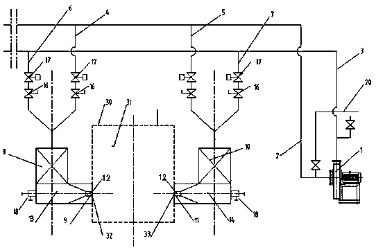
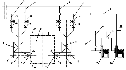
[0021] Such as figure 1 As shown, the regenerative forced furnace gas circulation device of the industrial furnace of the present invention includes a heating furnace body 30. The cavity in the middle of the heating furnace body 30 forms a furnace chamber 31. The workpiece to be heated is placed in the furnace chamber 31 to be heated and raised; the heating furnace body 30 Usually industrial furnaces such as electric furnaces and fuel furnaces. On the furnace 31, at least a pair of furnace first openings 32 and furnace second openings 33 are provided, that is, the furnace first opening 32 and the furnace second opening 33 are arranged in pairs, and the furnace first opening 32 and the furnace second opening 33 are respectively connected to The furnace 31 is connected, and when one of them is used as a blowing port for air intake, the other is used as an exhaust port for exhaust, which alternately takes in and exhausts to form an intake and exhaust circulation channel for flue ga...


PUM


Abstract

The invention discloses a heat accumulating type furnace gas forced circulation device of an industrial furnace. The furnace gas forced circulation device is arranged on an industrial furnace body and comprises a gas treatment unit. A first gas extracting branch pipeline body and a second gas extracting branch pipeline body are arranged on a gas extracting pipeline, and a first gas blowing branch pipeline body and a second gas blowing branch pipeline body are arranged on a gas blowing pipeline; and the first gas extracting branch pipeline body and the first gas blowing branch pipeline body as well as the second gas extracting branch pipeline body and the second gas blowing branch pipeline body communicate with a first heat accumulator and a second heat accumulator correspondingly under a controlled state, pipelines behind the first heat accumulator and the second heat accumulator are arranged to be matched with a first opening and a second opening of a hearth correspondingly, and gas in the hearth is extracted out or blown into by turns. In the heat accumulating type furnace gas forced circulation device of the industrial furnace, according to the principle of heat accumulator heat accumulating and releasing, furnace gas of an electric furnace and a fuel-fired furnace is subjected to forced furnace gas circulation and forced convection through a draught fan outside the furnace, homogeneity of the furnace temperature is greatly improved and reaches + / -3 DEG C or + / -5 DEG C, and the requirements for special material treatment are met; and forced furnace gas circulation, forced convection and forced agitation are conducted, furnace gas circulation is smooth, and homogeneity of the furnace temperature is remarkably improved.

Description

Technical field [0001] The invention relates to an industrial heating furnace, in particular to a regenerative forced furnace gas circulation device for industrial furnaces such as electric furnaces and fuel furnaces. Background technique [0002] For periodic industrial furnaces, such as electric furnaces, fuel furnaces, etc., the furnace temperature uniformity largely depends on the circulation intensity of the furnace gas in the furnace. The high furnace gas circulation intensity means the furnace temperature uniformity is high, and vice versa. Therefore, in order to improve the uniformity of the furnace temperature, a circulating fan is often set in the furnace, and the rotation of the fan generates agitation left and right to form a forced furnace gas circulation. These measures are effective when the furnace temperature is lower. However, for medium and high temperature furnaces, as the furnace temperature increases, the circulation fan is easily damaged at medium and high...

Claims


Application Information

Patent Timeline
Patent Type & Authority Patents(China)
IPC IPC(8): F27D7/04F27D17/00F28D20/00
CPCF27D7/04F27D17/004F27D2007/045F27D2017/007F28D20/00Y02E60/14
Inventor 项玮
Owner 项玮
Learn More