
Marine operation lamp

A work light and power supply technology, applied in lighting devices, fixed lighting devices, electric light sources, etc., can solve the problems of long time to sea and dangerous work lights, and achieve the purpose of preventing accidents, improving joint stability and improving work efficiency. Effect

Inactive Publication Date: 2017-07-18
余坚
View PDF5 Cites 5 Cited by
  • Summary
  • Abstract
  • Description
  • Claims
  • Application Information

AI Technical Summary

Problems solved by technology

Many ships that explore marine mineral resources need to be equipped with working lights that can cope with harsh environments due to the long time spent at sea. The existing working lights are all disassembled and assembled manually. Especially when the sea climate is not good, the working lights need to be replaced manually. very dangerous

Method used


Image

  • Marine operation lamp
  • Marine operation lamp
  • Marine operation lamp

Examples


Embodiment Construction

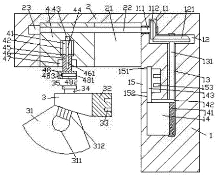
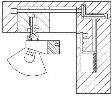
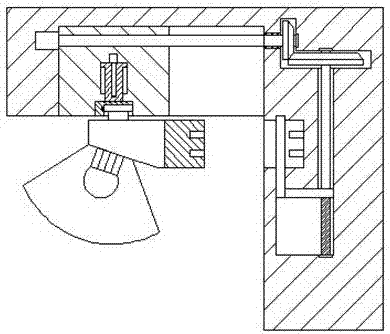
[0023] Such as Figure 1-Figure 7 As shown, a marine working light of the present invention includes a power feeding device 1, a sliding part 2 fixedly installed on the upper left side of the power feeding device 1, and a working light 3, and the bottom right side of the sliding part 2 is A sliding groove 21 is provided in the side surface, and a first screw 22 extending left and right is arranged in the sliding groove 21, and the left side of the first screw 22 is connected with the first electric rotating machine 23, and the first screw 22 The upper fitting is connected with a locking block 4 for locking and fitting connection with the work light 3, and the locking block 4 is in contact with the front and back of the sliding groove 21 and is connected by sliding fitting. The sliding groove 21 The power feeding device 1 on the right is provided with a first conduction cavity 11 extending up and down, and the bottom of the first conduction cavity 11 is penetrated with a second...


PUM


Abstract

The invention discloses a marine operation lamp which comprises a power supply device, a sliding portion and an operation lamp body. The sliding portion is fixedly installed above the left side of the power supply device. A sliding groove is formed in the side face of the bottom of the right side of the sliding portion. A first screw rod extending left and right is arranged in the sliding groove. The side face of the left side of the first screw rod is connected with a first electric rotation machine. A locking square block used for being in locked and matched connection with the operation lamp body is connected to the first screw rod in a matched mode, and the locking square block is connected with the front-back interior of the sliding groove in a sliding and matched mode. A first conductive cavity extending vertically is arranged in the portion, on the right side of the sliding groove, of the power supply device. A second conductive cavity extending to the right side is formed in the bottom of the first conductive cavity in a penetrating mode. A hollow cavity is formed in the side, away from the first conductive cavity, of the power supply device. A connection groove is formed in the side face of the side of the portion, above the left side of the hollow cavity, of the power supply device. The marine operation lamp is simple in structure, convenient to operate and capable of automatically controlling connection work.

Description

technical field [0001] The invention relates to the technical field of marine operation assistance, in particular to a marine operation light. Background technique [0002] Ocean engineering equipment is a subdivision of high-end equipment. Facing the major demand for marine resource development at home and abroad, the requirements for offshore operation assistance and services are getting higher and higher. Many ships that explore marine mineral resources need to be equipped with working lights that can cope with harsh environments due to the long time spent at sea. The existing working lights are all disassembled and assembled manually. Especially when the sea climate is not good, the working lights need to be replaced manually. very dangerous. Contents of the invention [0003] The technical problem to be solved by the present invention is to provide a marine working light, which can solve the above-mentioned problems in the prior art. [0004] The present invention i...

Claims


Application Information

Patent Timeline
Patent Type & Authority Applications(China)
IPC IPC(8): F21S8/00F21V19/04
CPCF21S8/00F21V19/04
Inventor 余坚
Owner 余坚
Learn More