Supercharge Your Innovation With Domain-Expert AI Agents!

Transmission mechanism provided with wedge sliding block

A technology of a wedge slider and a transmission mechanism is applied in the field of stamping devices, which can solve the problems of large occupied space and complex structure, and achieve the effects of simplified structure and low manufacturing and maintenance costs.

Inactive Publication Date: 2017-07-11
ANHUI JIANGHUAI AUTOMOBILE GRP CORP LTD
View PDF3 Cites 2 Cited by
  • Summary
  • Abstract
  • Description
  • Claims
  • Application Information

AI Technical Summary

Problems solved by technology

[0004] The present invention provides a wedge slider drive mechanism in order to solve the problem that the wedge drive mechanism in the prior art has a complex structure and occupies a large space

Method used


Image

  • Transmission mechanism provided with wedge sliding block
  • Transmission mechanism provided with wedge sliding block
  • Transmission mechanism provided with wedge sliding block

Examples


Embodiment 1

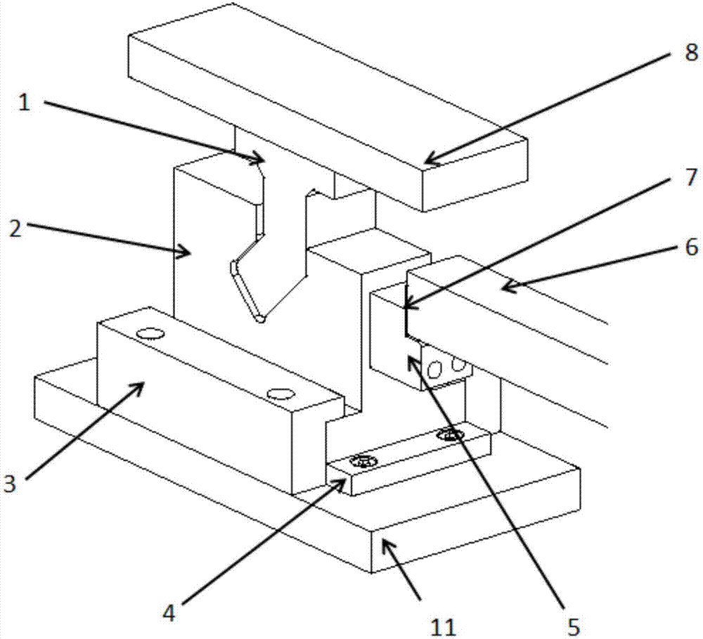
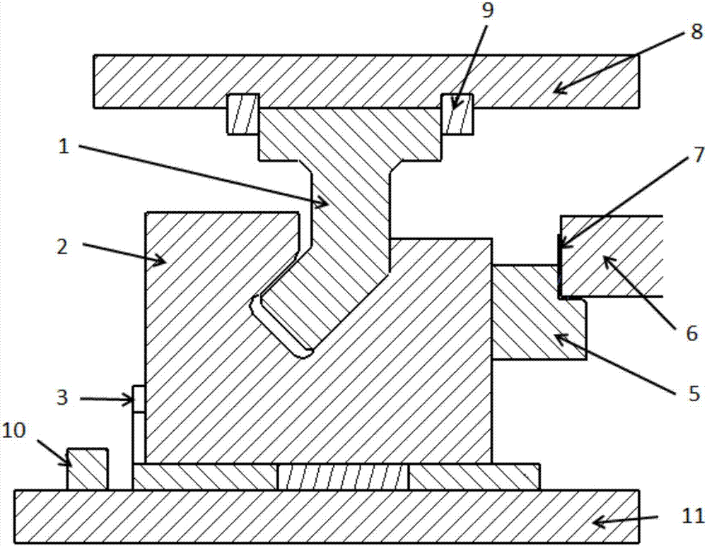
[0031] Realized by setting limit blocks on both sides of the wedge slider 2, combined with figure 1 and figure 2 As shown, specifically, a limit block is protruded from the lower template 11 on both sides of the wedge slider 2 along its moving direction, specifically the front limit block 4 on the front side and the rear limit block 10 on the rear side. , the wedge slider 2 moves between the two limit blocks, and the limit block limits the front and rear displacement of the wedge slider, so that the guide groove 21 opened on the wedge slider 2 faces the drive block 1 all the time.

Embodiment 2

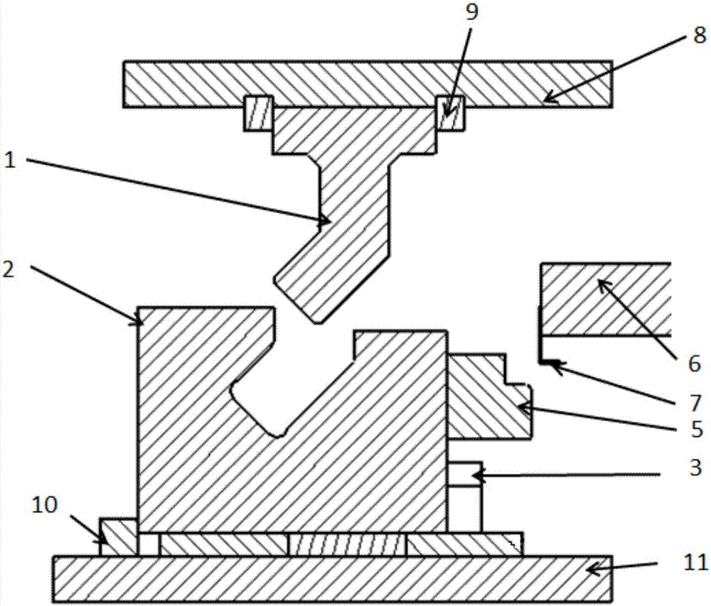
[0033] It is realized by setting the width of the guide groove 21 and the angle between the driving block 1 and the guide groove 21 . That is, in this embodiment, the guide groove 21 has a predetermined width. At this time, it should be ensured that the angle formed by the driving section of the driving block 1 and the driving direction of the upper template is an acute angle. The same, so the angle of its bending is also an acute angle. The adoption of the acute angle does not cause the mold to be too large to waste material, and when the drive block 1 cooperates with the guide groove 21, the lateral sliding distance of the wedge slider 2 will not be too large. Of course, Embodiment 1 and Embodiment 2 can also be used simultaneously to ensure that the bottom end of the drive block is always facing the opening of the guide groove.

[0034] Such as Figure 5 As shown, in the present embodiment, the guide groove 21 includes a vertical guide groove at the top and an inclined dr...


PUM


Abstract

The invention discloses a wedge slider transmission mechanism, which comprises a drive block fixed on the bottom side of an upper template and a wedge slider slidably installed on the top side of a lower template. One side of the wedge slider is fixed with a side shaping knife block. From top to bottom, the driving block is a vertical fixed section and a driving section inclined opposite to the driving direction of the wedge slider; a guide groove is provided on the top of the wedge slider, and the guide groove is close to the side shaping knife block. The inclined surface on the side is the driving surface, and the inclined surface on the side of the guide groove away from the side shaping knife block is the returning surface; when driving, the driving block cooperates with the driving surface, and there is a gap between the returning surface and the driving block; when returning, the driving The block cooperates with the return surface, and there is a gap between the driving surface and the driving block. This scheme completes the left and right movement of the slider through the direct cooperation of the drive block installed on the upper template with the wedge slider, so as to complete the shaping and withdrawal of the plastic knife block. There is no need to add a separate elastic part to return the slider to complete the exit. Simplified structure, low manufacturing and maintenance costs.

Description

technical field [0001] The invention relates to the field of stamping devices, in particular to a wedge slider transmission mechanism. Background technique [0002] The part processing method perpendicular to the stamping direction is a common processing method in the part processing process. At present, the driving method of the horizontal forming knife block adopts the form of a lifting wedge, that is, the upper and lower dies are each equipped with an oblique block. The oblique block of the block cooperates, and the downward movement of the upper inclined block and the lower inclined block cooperate to drive the horizontal movement of the side shaping knife block during the downward movement of the upper mold. The return stroke needs to be equipped with a spring dedicated to the return stroke. [0003] Because the components of this traditional wedge drive mechanism are relatively complex, the movement coordination between the various parts is relatively laborious and tak...

Claims


Application Information

Patent Timeline
IPC IPC(8): B21D37/12B21D1/00B21D3/00
CPCB21D37/12B21D1/00B21D3/00
Inventor 高双明胡晓妍戴冬华李辉徐肖刘峰井芊严嵒
Owner ANHUI JIANGHUAI AUTOMOBILE GRP CORP LTD
Features
  • R&D
  • Intellectual Property
  • Life Sciences
  • Materials
  • Tech Scout
  • Unparalleled Data Quality
  • Higher Quality Content
  • 60% Fewer Hallucinations
Learn More