
Camera shooting module assembling method and camera shooting module

A technology of camera module and assembly method, which is applied in the field of photography, and can solve problems such as increased defective products, sensor center deviation, and affecting image quality of camera modules, etc.

Active Publication Date: 2017-07-07
NANCHANG O FILM OPTICAL ELECTRONICS TECH CO LTD
View PDF5 Cites 15 Cited by
  • Summary
  • Abstract
  • Description
  • Claims
  • Application Information

AI Technical Summary

Problems solved by technology

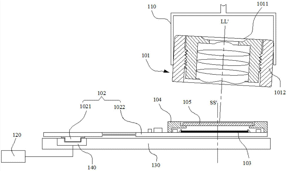
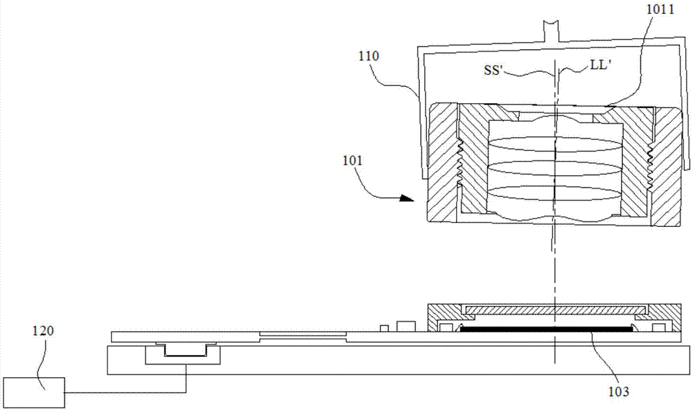
[0003] During the assembly process of the above-mentioned camera module, when grabbing the VCM, the VCM often tilts, causing the lens center of the lens in the VCM to deviate from the center of the Sensor on the circuit board, thereby affecting the imaging quality of the camera module, or causing defective products. Increase

Method used


Image

  • Camera shooting module assembling method and camera shooting module
  • Camera shooting module assembling method and camera shooting module
  • Camera shooting module assembling method and camera shooting module

Examples


Embodiment Construction

[0023] In order to facilitate the understanding of the present invention, the present invention will be described more fully below with reference to the associated drawings. A preferred embodiment of the invention is shown in the drawings. However, the present invention can be embodied in many different forms and is not limited to the embodiments described herein. Rather, these embodiments are provided so that the disclosure of the present invention will be thorough and complete.

[0024] It should be noted that when an element is referred to as being “fixed on” another element, it may be directly on the other element or there may be an intervening element. When an element is referred to as being "connected to" another element, it can be directly connected to the other element or intervening elements may also be present. The terms "vertical," "horizontal," "left," "right," and similar expressions are used herein for purposes of illustration only.

[0025] Unless otherwise d...


PUM


Abstract

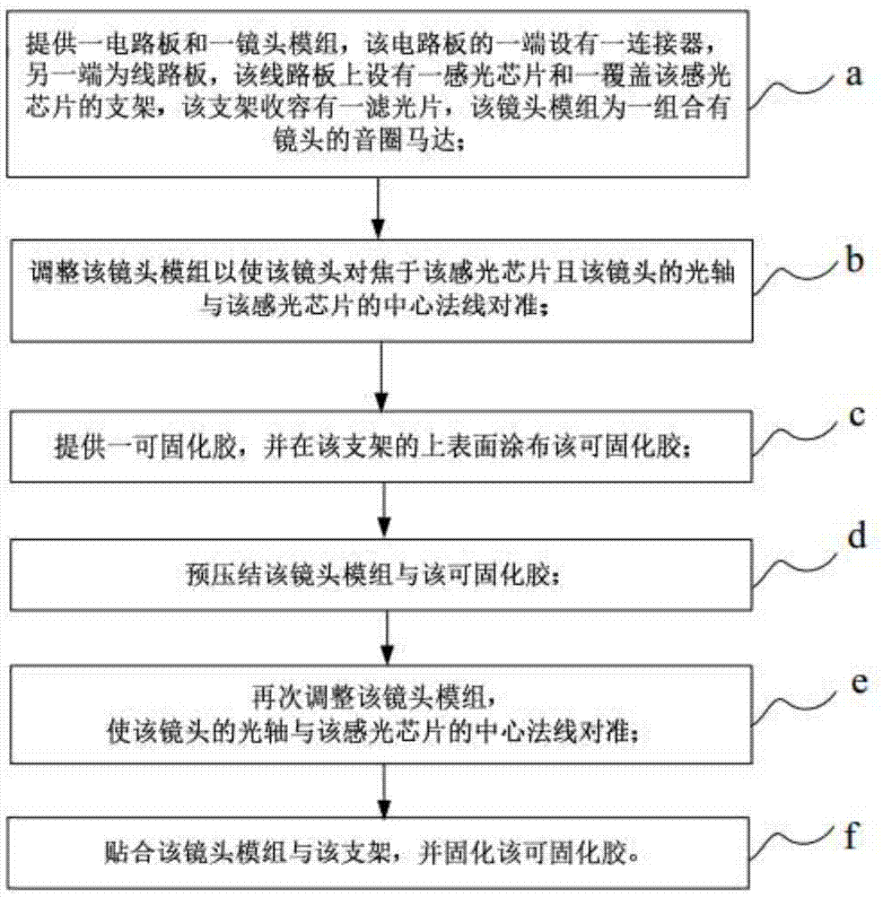
The invention relates to a camera shooting module assembling method, which comprises the steps of providing a circuit board and a lens module, wherein one end of the circuit board is provided with a connector, the other end is provided with a line board, the line board is provided with a photosensitive chip and a bracket covering the photosensitive chip, an optical fiber is accommodated in the bracket, and the lens module is a voice coil motor combined with a lens; adjusting the lens module so as to enable the lens to be focused to the photosensitive chip and enable an optical axis of the lens to be aligned to a central normal of the photosensitive chip; providing a curable adhesive, coating the upper surface of the bracket with the curable adhesive; pre-pressing the lens module and the curable adhesive; adjusting the lens module again so as to enable the optical axis of the lens to be aligned to the central normal of the photosensitive chip; and laminating the lens module and the bracket, and curing the curable adhesive. The invention further provides a camera shooting module. By adopting the camera shooting module assembling method, the assembling efficiency can be improved, the imaging quality of the camera shooting module can be ensured, and an adhesion force between the lens module and the bracket can be increased.

Description

technical field [0001] The invention relates to the field of camera technology, in particular to a method for assembling a camera module and a camera module. Background technique [0002] At present, a camera module with focusing function mainly includes a lens, a voice coil motor (VCM), a filter holder, a circuit board, and an image sensor (Sensor). The lens accommodates the lens, and the lens is matched with the VCM thread, and the VCM is used to drive the lens to move to realize the focusing function. When assembling, first install the Sensor on the top surface of the circuit board through Chip On Board (COB), and then dispense glue around the Sensor on the circuit board, and pass the filter holder containing the filter through the glue Paste on the circuit board, then dispense glue on the upper surface of the filter holder, grab the VCM combined with the lens by the extraction device to the position corresponding to the glue on the filter holder, and then glue the botto...

Claims


Application Information

Patent Timeline
IPC IPC(8): H04N5/225
CPCH04N23/54H04N23/50H04N23/57H04N23/55
Inventor 杨军涛陈礼贵
Owner NANCHANG O FILM OPTICAL ELECTRONICS TECH CO LTD
Learn More