
Elevated translation variable rail device, method of straddle type monorail railways and railways

A straddle-type monorail and track technology, applied in the direction of tracks, locking mechanisms for turnouts, roads, etc., can solve the problem of increasing the difficulty of design and construction of tracks, stations and transfer stations, difficulty in rail-changing operation of elevated platforms, and increasing construction. and maintenance costs, etc., to achieve the effect of large passenger carrying capacity, improved stability and reliability, and convenient implementation.

Inactive Publication Date: 2017-07-07
王国伟
View PDF0 Cites 8 Cited by
  • Summary
  • Abstract
  • Description
  • Claims
  • Application Information

AI Technical Summary

Problems solved by technology

[0004] But because the train of this rail vehicle is straddled on this elevated monorail beam, namely the bottom left and right sides of this train car covers part of the track beam, so greatly hinders the track changing ability of the train, especially, when the train needs to move from When one track is changed to another track, the difficulty of its implementation will be greatly increased. If the train cannot implement flexible and efficient track changes, it will greatly limit the operating capacity and efficiency of the rail vehicle, and at the same time increase the The design and construction of tracks, stations and transfer stations is difficult, and at the same station where two or more lines merge, passengers cannot transfer on the same platform at the station, which also increases construction and maintenance costs
[0005] At present, domestic monorail track changing devices can be divided into two types according to the structural form: joint-type track-changing devices and joint-flexible track-changing devices. The beam is approximately continuously bent into a curved line, so the two methods are large in size, complex in structure and difficult in operation and control, so it is difficult to implement rail switching operations on elevated platforms

Method used


Image

  • Elevated translation variable rail device, method of straddle type monorail railways and railways
  • Elevated translation variable rail device, method of straddle type monorail railways and railways
  • Elevated translation variable rail device, method of straddle type monorail railways and railways

Examples


Embodiment Construction

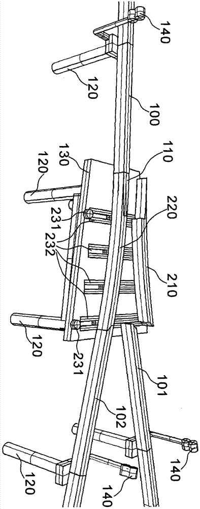
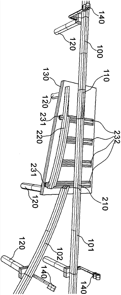
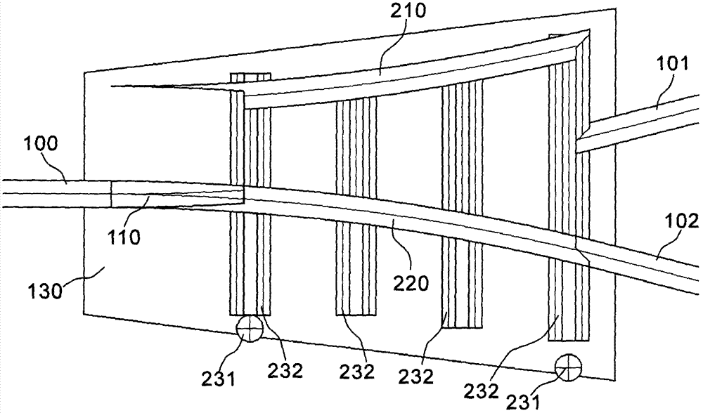
[0051] refer to figure 1 figure 2 Figure 3A Figure 3B Figure 4A Figure 4B An elevated translational rail changing device for a straddle-type monorail track, and the track includes a walking rail beam 100, a crossing track beam block 110, a first rail changing beam block 210, a second rail changing beam block 220, a rail changing actuator 230, and a track changing actuator 230. The rail locking mechanism 240, the signal light 140, the support column 120 and the installation platform 130 fixed on the top of the support column.

[0052] Two embodiments of the present invention are designed to be similar to " Y " shape structure (refer to figure 1 Figure 3A Figure 3B ) and the elevated straddle-type single-track track are designed to be similar to the "bu"-shaped structure (refer to figure 2 Figure 4A Figure 4B ).

[0053] refer to Figure 6A Figure 6B One end of the cross track beam block 110 is fixed to the corresponding end of the walking track beam 100,...


PUM


Abstract

The invention discloses an elevated translational rail changing device and a track of a straddle-type monorail track, comprising a walking rail beam, a cross track beam block, a first rail changing beam block, a second rail changing beam block, a rail changing actuator, a The rail locking mechanism, the signal lamp, the support column and the installation platform fixed on the top of the support column can change the positions of the first track change beam block and the second track change beam block through the track change actuator installed on the elevated installation platform to realize Different trains run on different elevated straddle monorails. Another solution of the present invention is to provide an elevated translational track change method for a straddle-type monorail track. The invention has the advantages of simple structure, stability, reliability and high efficiency.

Description

technical field [0001] The invention relates to a rail vehicle, in particular to an elevated translational rail changing device, method and track of a straddle-type monorail. Background technique [0002] In the face of urban environmental pollution and traffic congestion brought about by global urbanization, people seek a convenient and environmentally friendly urban transportation system. Ordinary cars are high-speed, convenient and fast, but when urban vehicles develop to a certain number, the traffic congestion caused by a large number of cars , tail gas pollution, dust pollution, and traffic accidents are becoming more and more prominent. Subway transportation and rail transportation have been developed in various places at the same time. The problems of high cost, long construction period and difficult construction are prominent. [0003] An existing means of transportation is a straddle-type monorail train system. The rail transit system is driven by electric power, ...

Claims


Application Information

Patent Timeline
IPC IPC(8): E01B25/12B61L5/10
CPCE01B25/12B61L5/102E01B2202/025E01B2202/048
Inventor 王国伟
Owner 王国伟
Learn More