Printed circuit board jig disassembling equipment

A printed circuit board and equipment technology, applied in the field of printed circuit board fixture decomposition equipment, can solve the problems of damaging the printed circuit board 103, increasing labor costs, and high rigidity of punching pins, so as to achieve semi-automatic operation and avoid punching pins from breaking , Optimizing the effect of the decomposition process

Pending Publication Date: 2017-07-07
广东新吉欣实业有限公司 +1
View PDF5 Cites 0 Cited by
  • Summary
  • Abstract
  • Description
  • Claims
  • Application Information

AI Technical Summary

Problems solved by technology

After the circuit board is transferred to the preset location, the PIN nail 104, the upper splint 101, and the printed circuit board 103 must be removed in sequence. Especially when taking the PIN nail 104, it is necessary to utilize a punching needle, a hammer, etc. to punch out the PIN nail 104. Due to the high rigidity of the punching needle, it is easy to break or cause personal injury, and the safety is poor. It will damage the printed circuit board 103, thereby causing adverse effects on the production process

Method used


Image

  • Printed circuit board jig disassembling equipment
  • Printed circuit board jig disassembling equipment
  • Printed circuit board jig disassembling equipment

Examples


Embodiment Construction

[0024] The present invention will be described in more detail below in conjunction with the accompanying drawings and embodiments.

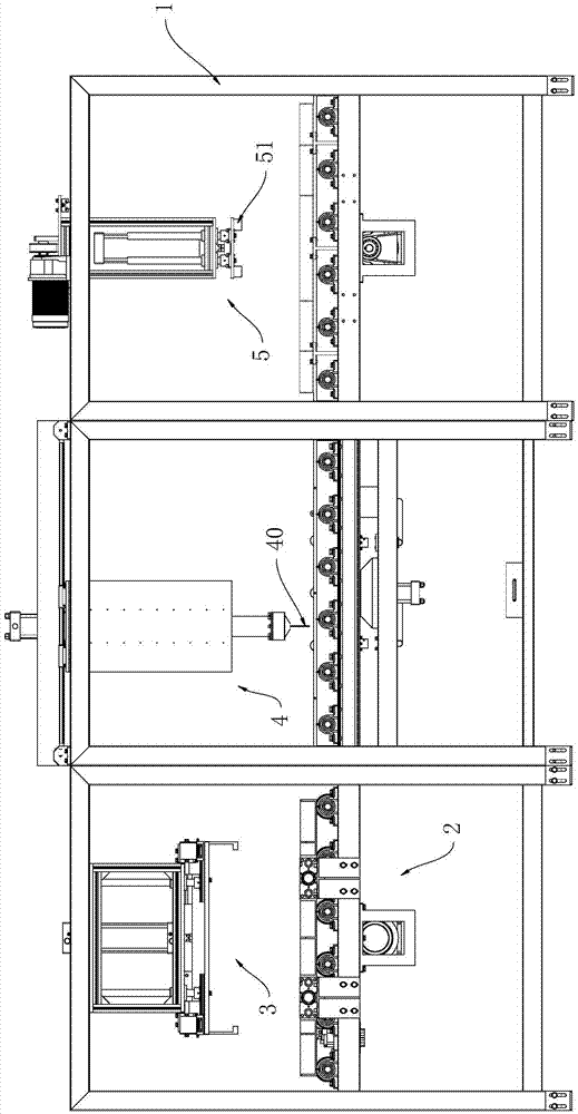
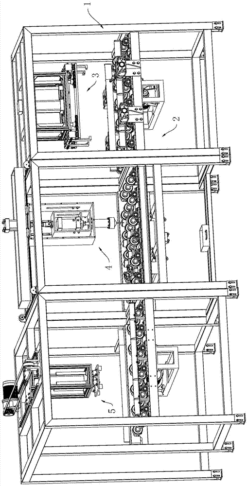
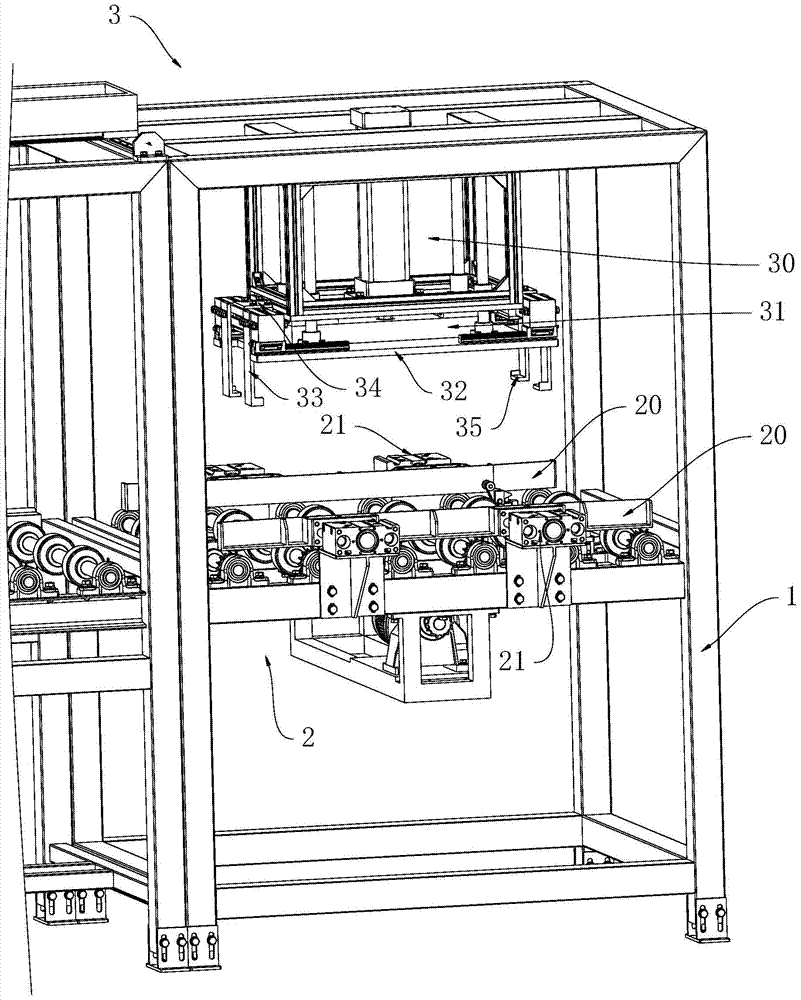
[0025] The invention discloses a printed circuit board jig decomposition device, which combines Figure 1 to Figure 8 As shown, it includes a frame 1, and the frame 1 is provided with a conveying mechanism 2, and above the conveying mechanism 2 and along the conveying direction, a feeding mechanism 3, a PIN returning mechanism 4 and an unloading mechanism 5 are sequentially arranged. ,in:

[0026] The conveying mechanism 2 is used to convey the printed circuit board jig 100;

[0027] The feeding mechanism 3 is used to clamp the printed circuit board jig 100 and place it on the conveying mechanism 2;

[0028] The PIN withdrawal mechanism 4 includes a punching needle 40, and the PIN withdrawal mechanism 4 is used to first align the punching needle 40 with the PIN nail 104 of the printed circuit board jig 100, and then apply a force to the punchin...


PUM


Abstract

The invention discloses printed circuit board jig disassembling equipment which comprises a rack; a delivery mechanism is arranged on the rack; a charging mechanism, a PIN withdrawing mechanism and a discharging mechanism are arranged above the delivery mechanism and in the delivery direction sequentially; the delivery mechanism is used for delivering a printed circuit board jig; the charging mechanism is used for clamping the printed circuit board jig and putting the printed circuit board jig on the delivery mechanism; the PIN withdrawing mechanism comprises a punching pin, and is used for aligning the punching pin with each PIN nail of the printed circuit board jig and then applying impulse force to the punching pin to withdraw the corresponding PIN nail; and the discharging mechanism is used for taking down an upper clamping plate, a printed circuit board and a lower clamping plate of the printed circuit board jig sequentially. The printed circuit board jig disassembling equipment has the beneficial effects that semi-automatic operation can be realized, the working efficiency is high, the labor cost is low, potential safety hazards are reduced, and a product is prevented from being damaged.

Description

technical field [0001] The invention relates to the technical field of printed circuit board transmission, in particular to a printed circuit board fixture decomposition device. Background technique [0002] Such as Figure 8 As shown, the printed circuit board needs to be clamped and fixed by the printed circuit board fixture 100 during the transfer process. The printed circuit board fixture 100 includes an upper splint 101 and a lower splint 102. The printed circuit board 103 is sandwiched between the upper splint 101 and the lower splint 102. Between the lower splints 102, the through holes of the upper splint 101, the through holes of the printed circuit board 103 and the through holes of the lower splint 102 are sequentially passed through the PIN nails 104, and multiple PIN nails 104 can be used to align the upper splint 101 and the printed circuit board. The plate 103 and the lower clamping plate 102 are positioned, and then the printed circuit board jig 100 is placed...

Claims


Application Information

Patent Timeline
IPC IPC(8): B23P19/027
CPCB23P19/001B23P19/007B23P19/025B23P19/027
Inventor 谭义满钟曙光徐振中
Owner 广东新吉欣实业有限公司
Why Eureka
Try Eureka