Eureka AIR delivers breakthrough ideas for toughest innovation challenges, trusted by R&D personnel around the world.

Housing device for motor

A shell and purpose technology, applied in the field of shell devices, can solve the problems of expensive manufacturing and processing technology, and achieve the effect of compact arrangement, saving installation space, and easy installation

Active Publication Date: 2017-07-04
VOLKSWAGEN AG
View PDF7 Cites 4 Cited by
  • Summary
  • Abstract
  • Description
  • Claims
  • Application Information

AI Technical Summary

Problems solved by technology

The radial construction space available is usually only 10mm to 20mm, which makes manufacturing expensive due to complex processing techniques

Method used


Image

  • Housing device for motor
  • Housing device for motor
  • Housing device for motor

Examples


Embodiment Construction

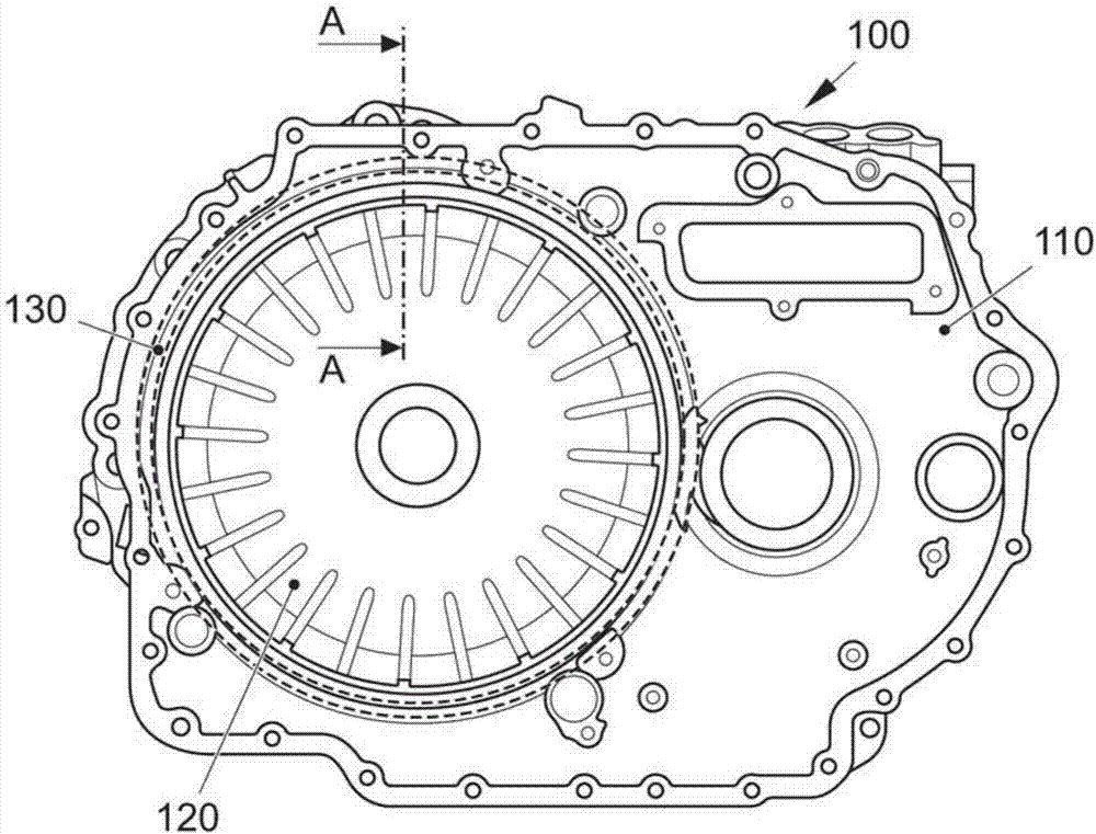
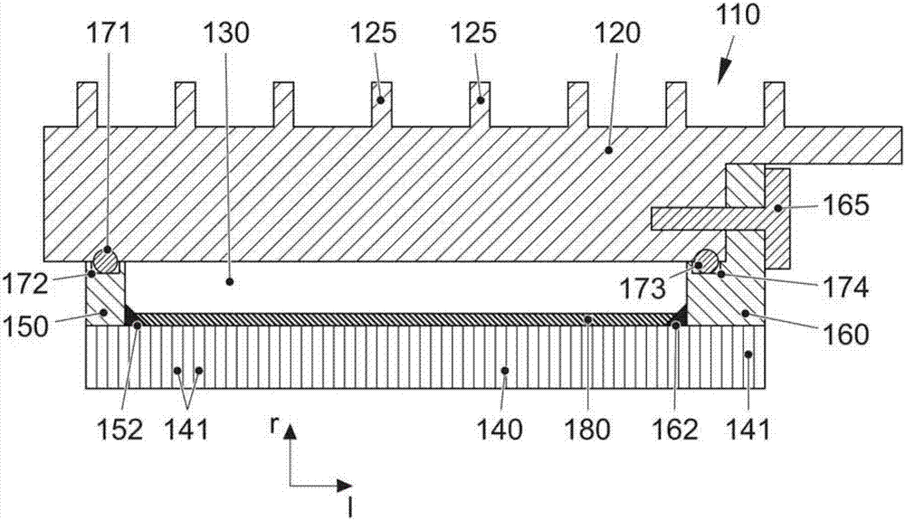
[0026] figure 1 A hybrid drive housing part 110 for a hybrid drive 100 of a motor vehicle (passenger car) with a hybrid drive is shown. The housing part 110 is a lightweight metal and in particular aluminum die-cast part. Reference numeral 120 denotes a stator receiving area designed as a cup-shaped cavity (cavity) for an electric machine (traction motor) and / or generator arranged in hybrid drive 100 . During operation, the electric motor and / or generator must be actively cooled in order to dissipate the heat generated reliably. In this case, a cooling channel or cooling jacket 130 is provided surrounding the stator receiving region or the stator receiving section 120 , through which cooling channel or cooling jacket 130 a coolant can circulate. The dotted circle shows that the annular cooling jacket 130 has an inner diameter of, for example, 250 mm to 300 mm. A cooling structure (not shown) designed as an insert can be arranged in the interior of the integrated cooling jac...


PUM


Abstract

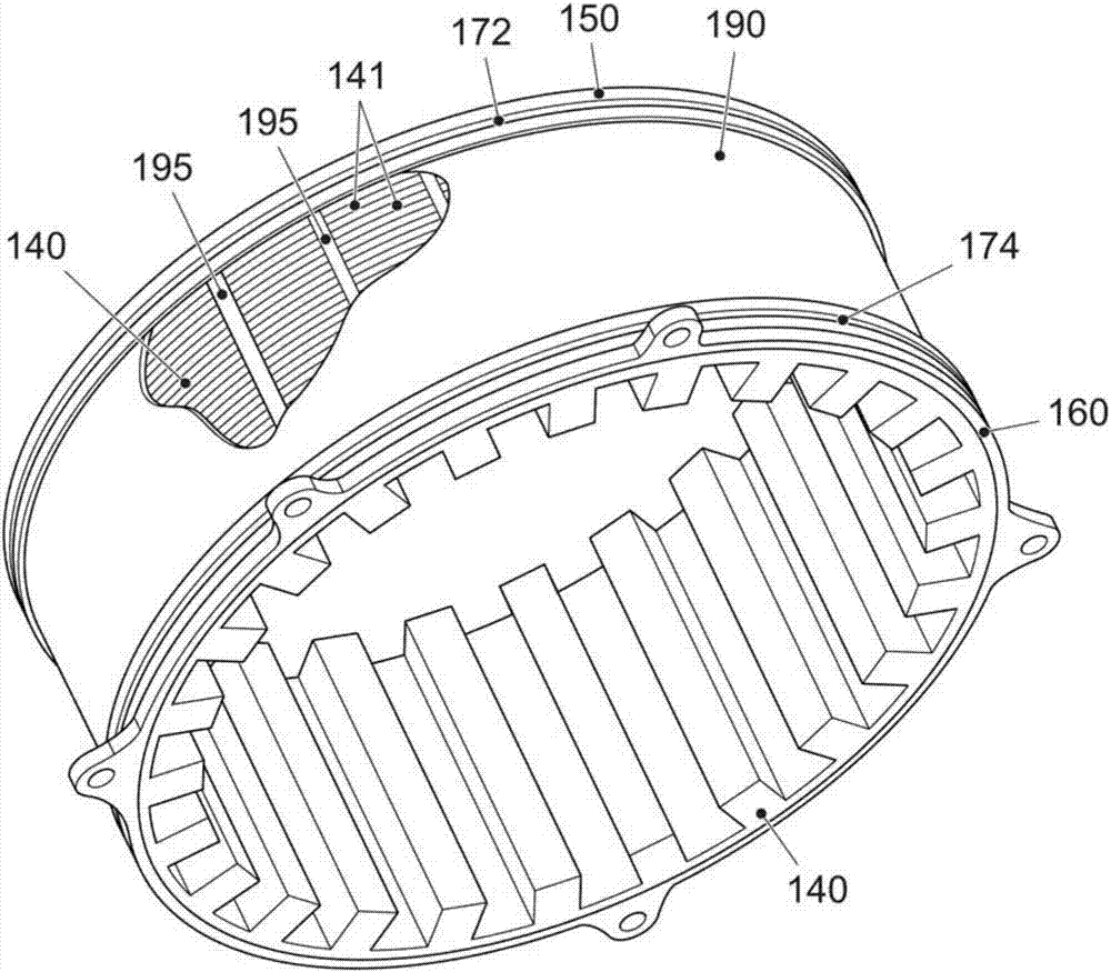
The present invention relates to a housing device for a motor (such as a motor and / or a generator), comprising a housing (110) having a stator holding area (120); a stator (140) arranged in the stator holding area (120) of a housing (110); and a cooling sleeve (130) configured for liquid cooling of a stator (140), wherein the outer wall of the stator (140) forms an internal cooling sleeve surface of the cooling sleeve (130).

Description

technical field [0001] The invention relates to a housing arrangement for an electric motor, which has a housing with (at least one) stator receiving area, a stator of the electric machine arranged in the stator receiving area of ​​the housing, and a stator for the stator surrounding the stator. Cooling jacket for liquid cooling. Background technique [0002] The electric machine is an electromechanical converter which converts electrical energy into mechanical energy and / or mechanical energy into electrical energy. In particular, they are electric motors (electric motors) and / or generators with a stationary stator or carrier and a rotor or rotor (inner rotor) mounted rotatably in the stator. [0003] When used in the field of vehicles, for example as a traction engine or drive engine and / or generator (vehicle generator), the electric motor can be arranged in the housing on the side of the stator, wherein due to the high power and limited installation space High power dens...

Claims


Application Information

Patent Timeline
Patent Type & Authority Applications(China)
IPC IPC(8): H02K5/20H02K9/19
CPCH02K5/203
Inventor A.布劳恩
Owner VOLKSWAGEN AG
Why Eureka
Eureka Blog
Learn More