
Connecting plate of capacitor

A technology for connecting plates and capacitors, applied in the direction of capacitors, electrical components, etc., can solve problems such as complex structure, and achieve the effects of simple structure, high production efficiency, and simple and fast fixing operation.

Inactive Publication Date: 2017-07-04
宁波新容电器科技有限公司
View PDF0 Cites 0 Cited by
  • Summary
  • Abstract
  • Description
  • Claims
  • Application Information

AI Technical Summary

Problems solved by technology

[0004] The problem to be solved by the present invention is to provide a capacitor connection plate to overcome the defects of complex structure in the prior art

Method used


Image

  • Connecting plate of capacitor

Examples


Embodiment Construction

[0011] The specific implementation manners of the present invention will be further described in detail below in conjunction with the accompanying drawings and embodiments. The following examples are used to illustrate the present invention, but are not intended to limit the scope of the present invention.

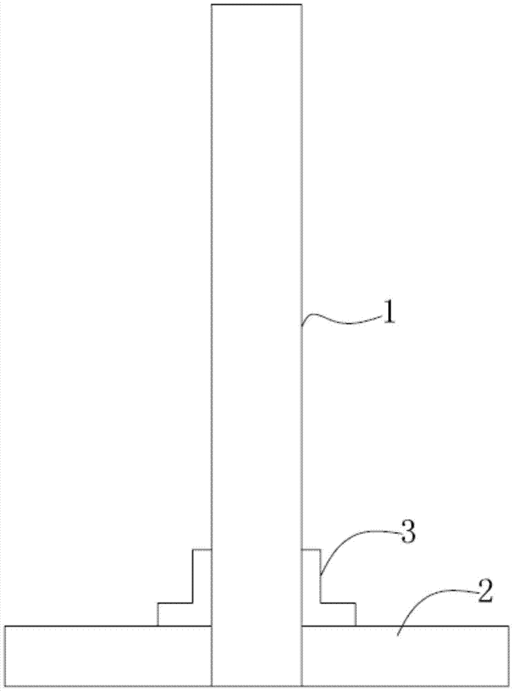
[0012] Such as figure 1 As shown, a capacitor connection plate of the present invention includes a main body 1 and a bracket 2; the bracket 2 is fixed on both sides of the lower end of the main body 1; The buckle 3 is fixed to the main body 1 and the bracket 2 respectively. The lock buckle 3 is L-shaped.

[0013] In summary, the above-mentioned embodiments are not limiting embodiments of the present invention, and all modifications or equivalent deformations made by those skilled in the art on the basis of the essence of the present invention are within the technical scope of the present invention.


PUM


Abstract

The invention provides a connecting plate of a capacitor. The connecting plate comprises a main body and a bracket; the bracket is fixed on the two sides of the low end of the main body; lock catches are arranged in combination places between the main body and the bracket on two sides; and each lock catch is fixed with the main body and the bracket separately. The connecting plate has simple structure, simple, rapid and convenient fixation operation, and high production efficiency.

Description

technical field [0001] The invention relates to a capacitor connecting plate. Background technique [0002] Capacitors, usually referred to simply as their ability to hold charges, are capacitance. Definition 1: A capacitor, as the name implies, is a 'charged container', a device that holds charges. Capacitors are one of the electronic components widely used in electronic equipment, and are widely used in DC blocking, coupling, bypass, filtering, tuning loops, energy conversion, control, etc. in circuits. Definition 2: Capacitor, any two conductors (including wires) that are insulated from each other and are very close to each other form a capacitor. The existing capacitor connecting plate has a complex structure. Contents of the invention [0003] (1) Technical problems to be solved [0004] The problem to be solved by the present invention is to provide a capacitor connection plate to overcome the defects of complex structure in the prior art. [0005] (2) Technical...

Claims


Application Information

Patent Timeline
Patent Type & Authority Applications(China)
IPC IPC(8): H01G2/00
CPCH01G2/00
Inventor 贾德星
Owner 宁波新容电器科技有限公司
Learn More