
Determination method of deepwater gas well blowout flow rate

A technology to determine the method and flow rate, which is applied in special data processing applications, instruments, electrical digital data processing, etc., and can solve the problems that the underwater wellhead cannot be shut down, the blowout flow rate cannot be obtained, and the blowout flow rate cannot be determined.

Active Publication Date: 2017-07-04
CHINA NAT OFFSHORE OIL CORP +1
View PDF3 Cites 0 Cited by
  • Summary
  • Abstract
  • Description
  • Claims
  • Application Information

AI Technical Summary

Problems solved by technology

During deepwater gas well drilling, the blowout preventer is underwater. When a strong blowout occurs and the well cannot be shut down, the blowout source is generally at the bottom of the well, and the blown gas flows to the sea surface in the form of a plume. At this time, the blowout flow rate cannot be obtained.
Conventional methods such as mass flow meters or measuring the gas injection height cannot be used in deep-water gas wells with serious blowouts and underwater wellheads that cannot be shut down
Therefore, after the deep-water gas well blowout occurs, if the deep-water gas well blowout is serious and the underwater wellhead cannot be shut down, the existing method will not be able to determine the blowout flow rate.

Method used


Image

  • Determination method of deepwater gas well blowout flow rate
  • Determination method of deepwater gas well blowout flow rate
  • Determination method of deepwater gas well blowout flow rate

Examples


Embodiment Construction

[0095] The present invention will be described in detail below in conjunction with the accompanying drawings and embodiments.

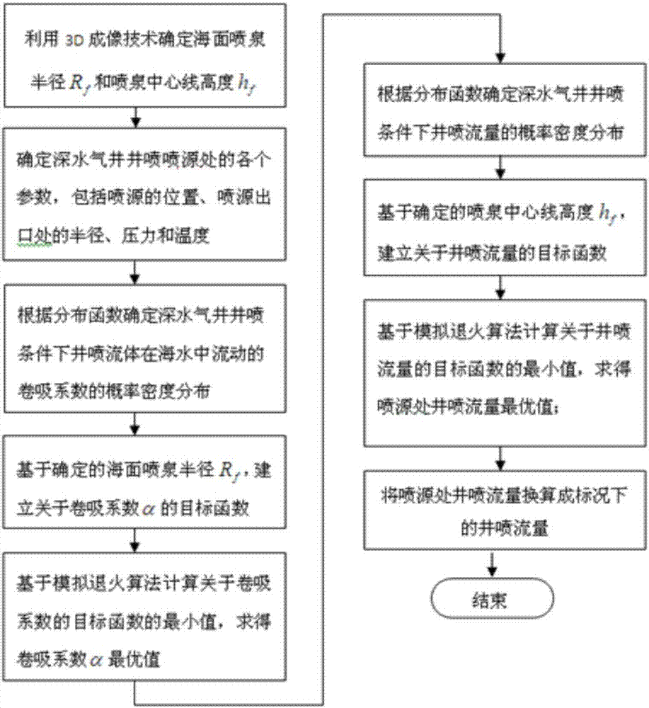
[0096] Such as figure 1 As shown, the present invention provides a method for determining the blowout flow rate of a deep-water gas well, comprising the steps of:

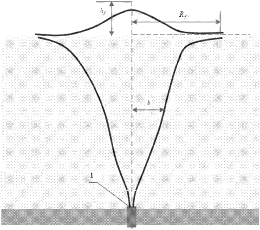
[0097] 1) Use 3D imaging technology to determine the radius R of the sea fountain f and fountain centerline height h f (Such as figure 2 shown).

[0098] 2) Determine various parameters at the blowout source 1 of the deep-water gas well, including the position of the blowout source 1, the radius, pressure and temperature at the outlet of the blowout source 1.

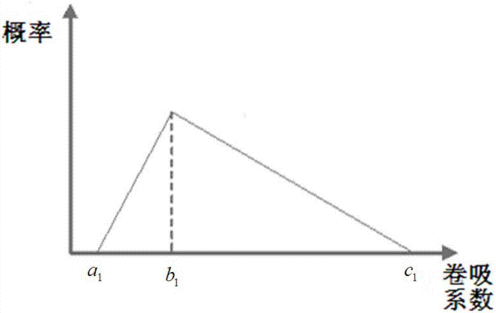
[0099] 3) Determine the probability density distribution of the entrainment coefficient of the blowout fluid flowing in the seawater under the blowout condition of the deep-water gas well, and the probability density distribution is a triangular distribution (such as image 3 shown), the distribution function is:

[0100] ...


PUM


Abstract

The invention relates to a determination method of a deepwater gas well blowout flow rate. The method comprises the steps that (1) a 3D imaging technology is used to determine a sea face fountain radius Rf and a fountain center line height hf; (2) different parameters at a blowout source of a deepwater gas well, including a blowout source position, as well as the radius, pressure and temperature at the blowout source outlet are determined; (3) probability density distribution of entrainment coefficients of a blowout fluid under the deepwater gas well blowout condition is determined; (4) based on the sea face fountain radius Rf, a target function relative to the entrainment coefficient alpha is established; (5) a minimum value of the target function relative to the entrainment coefficient is computed based on a simulated annealing algorithm, and the optimal value of the entrainment coefficient alpha can be worked out; (6) probability density distribution of blowout flow rates is determined; (7) based on the fountain center line height hf, a target function relative to the blowout flow rates is established; (8) the minimum value of the target function relative to the blowout flow rates is computed based on the simulated annealing algorithm, and the optimal value V0 of the blowout flow rate at the blowout source can be worked out; and (9) the optimal value V0 of the blowout flow rate at the blowout source is converted into a blowout flow rate under standard conditions.

Description

technical field [0001] The invention relates to a method for determining the blowout flow rate, in particular to a method for determining the blowout flow rate of a deep-water gas well when the underwater wellhead cannot be shut down, and belongs to the field of offshore oil engineering. Background technique [0002] In the process of deepwater drilling, the safe mud density window is narrow, formation pressure and fluid invasion are ambiguous, random and uncertain, and unclear understanding of objective conditions or subjective decision-making mistakes will cause many complicated situations or serious accidents. The light ones consume a lot of manpower, material resources and time, and the serious ones lead to strong blowouts, blowouts out of control and unable to shut down the well. After a blowout of a deepwater gas well occurs, emergency rescue operations and follow-up unconventional well killing operations should be carried out quickly to achieve re-control of the wellb...

Claims


Application Information

Patent Timeline
Patent Type & Authority Applications(China)
IPC IPC(8): G06F19/00
CPCG16Z99/00
Inventor 李梦博许亮斌罗洪斌耿亚楠
Owner CHINA NAT OFFSHORE OIL CORP
Learn More