
Safety protection system of logging-while-drilling apparatus

A logging-while-drilling tool and safety protection technology, applied in the field of drilling equipment, can solve problems such as affecting work efficiency, low degree of automation, damage to parameter subsections, etc., and achieve the effect of meeting heat dissipation requirements, scientific and reasonable design, and high degree of automation.

Inactive Publication Date: 2017-07-04
天津中新安德科技有限公司
View PDF6 Cites 0 Cited by
  • Summary
  • Abstract
  • Description
  • Claims
  • Application Information

AI Technical Summary

Problems solved by technology

[0002] At present, the new type of LWD system is usually carried out at the wellhead on site due to the fact that there are many drill pipes installed in the central hole and the mass of each parameter sub-section is very large. Assembling, due to the complex operation of the wellhead and many unforeseen problems, the personal safety of the operators cannot be guaranteed, especially during installation, the parameter nipples hanging on the upper part are easy to shake or even fall, which will easily affect the normal operation of the operators. Installation, and it is not easy to connect with the lower parameter pup joint, which affects work efficiency
For this reason, the Chinese invention patent No. 201320126965.6 discloses a logging-while-drilling tool safety protection system, which can realize fast docking, is safe and reliable, can ensure the personal safety of operators, and improves work efficiency, but there are still The above defects: 1. The movement of the upper and lower stoppers needs to be realized manually, and the degree of automation is low; 2. The outer wall of the parameter nipple is easy to rigidly collide with the cutout, resulting in damage to the parameter nipple; 3. When the connecting plug cannot be connected, the parameter is short Knuckle non-rotatable adjustment

Method used


Image

  • Safety protection system of logging-while-drilling apparatus

Examples


Embodiment Construction

[0012] In order to make the technical means, creative features, goals and effects achieved by the present invention easy to understand, the present invention will be further described below in conjunction with specific embodiments.

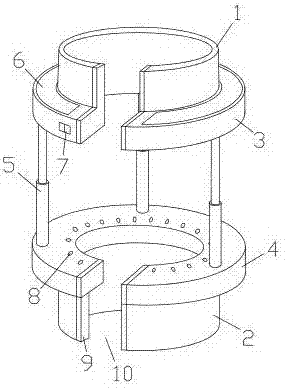
[0013] Such as figure 1 As shown, a logging-while-drilling tool safety protection system includes an upper chuck 1, a lower chuck 2, an upper stopper 3, a lower stopper 4, a telescopic arm 5, a power supply 6, a switch 7, a ball 8 and an anti-collision Pad 9; the upper chuck 1 is fixed at the upper mouth of the upper baffle, the lower chuck 2 is fixed at the lower mouth of the lower baffle 4, and the telescopic arm 5 is fixed between the upper baffle 3 and the lower baffle 4; One side of the upper baffle plate 3, the lower baffle plate 4, the upper chuck 1 and the lower chuck 2 is provided with co-located longitudinal cuts 10, and the inner walls of the two cuts 10 are adhered with anti-collision plates for protecting the short joints of parameter...


PUM


Abstract

The invention discloses a safety protection system of a logging-while-drilling apparatus. The safety protection system comprises an upper chuck, a lower chuck, an upper stopping disk, a lower stopping disk, telescopic arms, a power supply, a switch, balls and anti-collision cushions. The safety protection system is characterized in that the upper chuck is fixed at an upper opening of the upper stopping disk; the lower chuck is fixed at a lower opening of the lower stopping disk; longitudinal notches are formed in the same positions of one side of the upper chuck, the lower chuck, the upper stopping disk and the lower stopping disk; the anti-collision cushions for protecting parameter short sections are stuck on inner walls of the two notches; a mounting groove is formed in an upper surface of the upper stopping disk; a power supply is fixed inside the mounting groove. According to the safety protection system of the logging-while-drilling apparatus, the upper and lower stopping disks can be moved without the need of manpower and the automation degree is high; heat dissipation requirements can be met and seawater cannot enter a cabinet body, so that a machine body is effectively protected; the anti-collision cushions are mounted on the notches and the parameter short sections are effectively protected from damages; when connecting plugs cannot be in butt joint, the parameter short sections can be rotatably adjusted, so that angles of the connecting plugs are changed and the safety protection system is convenient to mount.

Description

technical field [0001] The invention relates to a protection device, in particular to a safety protection system of a logging-while-drilling instrument, which belongs to the technical field of drilling equipment. Background technique [0002] At present, the new type of LWD system is usually carried out at the wellhead on site due to the fact that there are many drill pipes installed in the central hole and the mass of each parameter sub-section is very large. Assembling, due to the complex operation of the wellhead and many unforeseen problems, the personal safety of the operators cannot be guaranteed, especially during installation, the parameter nipples hanging on the upper part are easy to shake or even fall, which will easily affect the normal operation of the operators. It is not easy to be connected with the parameter pup joint at the lower part, which will affect the work efficiency. For this reason, the Chinese invention patent No. 201320126965.6 discloses a loggin...

Claims


Application Information

Patent Timeline
Patent Type & Authority Applications(China)
IPC IPC(8): B25B27/00
CPCB25B27/00
Inventor 王焕英
Owner 天津中新安德科技有限公司
Learn More