
Energy storage and electrolyte mixing system for flow battery, and control method thereof

A technology of liquid flow battery and energy storage system, which is applied in the direction of fuel cells, fuel cell additives, circuits, etc., and can solve problems such as threats to the safe operation of the system, capacity decline of the liquid flow battery energy storage system, and liquid level difference. The effect of system capacity reduction

Inactive Publication Date: 2017-06-30
湖南德沃普电气股份有限公司
View PDF6 Cites 14 Cited by
  • Summary
  • Abstract
  • Description
  • Claims
  • Application Information

AI Technical Summary

Problems solved by technology

When the flow battery is in normal operation, the electrolyte is always in a flowing state. Therefore, after a period of operation, the liquid level in the positive and negative electrolyte storage tanks may be inconsistent, that is, there will be a liquid level difference, which will cause the flow battery to store energy. The system capacity decreases, even threatening the safe operation of the system

Method used


Image

  • Energy storage and electrolyte mixing system for flow battery, and control method thereof
  • Energy storage and electrolyte mixing system for flow battery, and control method thereof

Examples


Embodiment

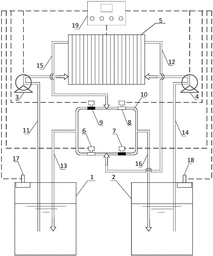
[0044] Such as figure 1 As shown, the flow battery energy storage mixed liquid system includes: positive electrolyte liquid storage tank 1, negative electrode electrolyte liquid storage tank 2, positive electrode electrolyte magnetic drive circulation pump 3, negative electrode electrolyte magnetic force drive circulation pump 4, stack 5, Battery management system BMS19, positive electrode stacking pipeline 11, positive electrode stacking pipeline 12, positive electrode tanking pipeline 13, negative electrode stacking pipeline 14, negative electrode stacking pipeline 15, negative electrode tanking pipeline 16, positive electrode liquid level Sensor 17, negative electrode liquid level sensor 18, mixed liquid pipeline;

[0045] The above mixed liquid pipeline includes: a loop 10, a positive electrode normal solenoid valve 6, a positive electrode mixed liquid solenoid valve 7, a negative electrode normal electromagnetic valve 8, and a negative electrode mixed liquid solenoid valv...


PUM


Abstract

The invention specifically relates to an energy storage and electrolyte mixing system for a flow battery, and a control method thereof, belonging to the field of energy storage of flow batteries. The energy storage and electrolyte mixing system for the flow battery comprises a positive electrolyte storage tank, a negative electrolyte storage tank, a magnetic force-driven circulating pump for a positive electrolyte, a magnetic force-driven circulating pump for a negative electrolyte, a battery management system (BMS), a positive in-pile pipeline, a positive out-of-pile pipeline, a positive in-tank pipeline, a negative in-pile pipeline, a negative out-of-pile pipeline, a negative in-tank pipeline, a positive electrolyte level sensor, a negative electrolyte level sensor and an electrolyte mixing pipeline. According to the invention, through introduction of the electrolyte mixing pipeline, the electrolyte mixing system can be easily and ingeniously switched between two working modes, i.e., a normal working mode and an electrolyte mixing mode; so the problem of decrease in system capacity is overcome, or even, potential safety hazards of the system are avoided.

Description

[0001] Technical field: [0002] The invention relates to the field of flow battery energy storage, in particular to a flow battery energy storage mixed liquid system and a control method thereof. [0003] Background technique: [0004] Liquid flow battery is one of the excellent green batteries with strong development momentum at present. It has obvious advantages such as high power, long life, and deep and high current density charging and discharging. It has become one of the main commercial development directions in the battery system. In wind power , photovoltaic power generation, power grid peak regulation and other fields have extremely broad application prospects. However, the current all-vanadium redox flow battery technology is not mature enough, and there are many problems. The remarkable feature of the flow battery system and other non-flow battery systems is that the flow battery needs to use the positive and negative electrolyte magnetic drive circulation pump to...

Claims


Application Information

Patent Timeline
Patent Type & Authority Applications(China)
IPC IPC(8): H01M8/04276H01M8/04992
CPCH01M8/04276H01M8/04992Y02E60/50
Inventor 魏达刘平平刘杰
Owner 湖南德沃普电气股份有限公司
Learn More