Device and method for recovering original CT projection data, and CT imaging system
A technology of projecting data and CT images, applied in the field of X-ray imaging, can solve the problem that the quality of reconstructed images cannot be effectively improved
- Summary
- Abstract
- Description
- Claims
- Application Information
AI Technical Summary
Problems solved by technology
Method used
Image

Examples
no. 1 example
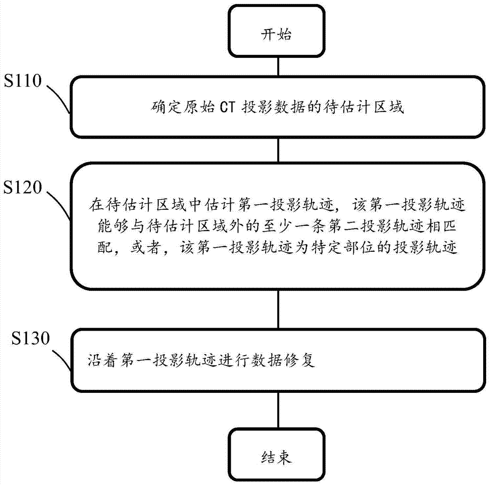
[0030] figure 1 It is a flow chart of the method for restoring original CT projection data provided by the first embodiment of the present invention. Those skilled in the art can understand that the above-mentioned original CT projection data can be, for example, projection data collected from a detector channel of a CT imaging system, or projection data that has undergone some preprocessing after collection, and the preprocessing can include: For example, offset (Offset) correction to remove dark current, reference (Reference) channel correction to remove the fluctuation of ray energy in each field of view, air (aircal) correction to remove the inhomogeneity of the initial energy of each channel, beam hardening correction to remove high and low energy rays The absorption rate is inconsistent, and the -In mathematical transformation makes the data theoretically become the meaning of summation, etc.
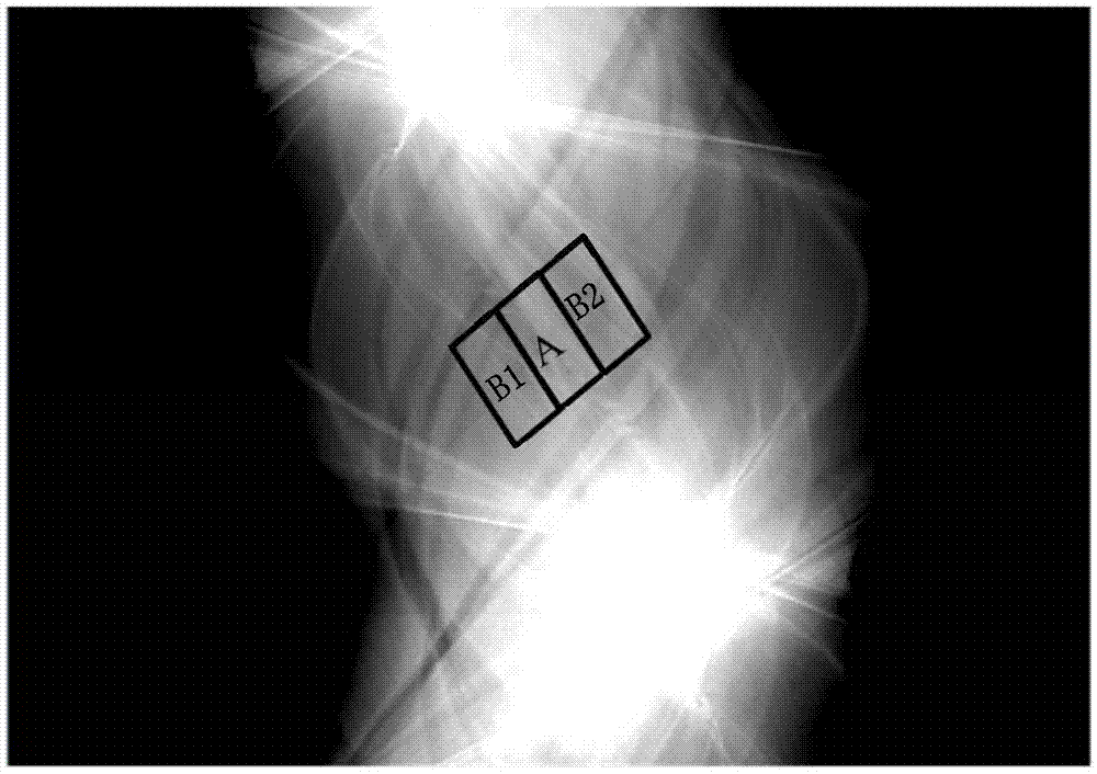
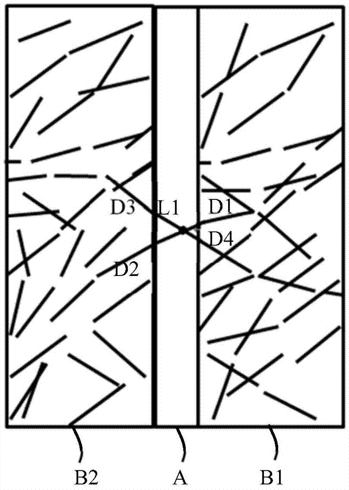
[0031] figure 2 It is a schematic diagram of the original CT projection da...
no. 2 example
[0071]During the CT scanning imaging process, when the scanned object is too large or placed off-center, a part of the scanned object will be located outside the coverage of the detector. In this way, a part of the original CT projection data cannot be displayed in the original CT projection image. In this embodiment, this part of the CT projection data is called truncated data. In projected space, the region where the truncated data resides is called the truncated region.
[0072] In the second embodiment, when the original CT projection data is truncated, it is necessary to re-estimate the CT projection trajectory of the truncated region and the data on it. At this time, the CT projection trajectory of the truncated region is used as the first projection trajectory, which needs to be able to At least one truncated CT projection trajectory in the original CT projection data is connected into a complete projection trajectory.
[0073] The method for repairing original CT proj...
no. 3 example
[0099] As shown above, due to the performance degradation of some channels on the detector, the scanned object contains metal, etc., the original CT projection data will contain low-reliability data, and the CT original image obtained by using these data to participate in the reconstruction will appear Artifacts.
[0100] In the third embodiment, in the CT projection trajectory obtained by forward projection of the original CT image, when the credible projection trajectory overlaps the uncredible strip or linear projection trajectory, it is necessary to estimate the credible projection trajectory at The texture direction of the overlapping area, and perform data restoration along the texture direction.
[0101] Similar to the first and second embodiments, the method for repairing original CT projection data in the third embodiment of the present invention includes the above step of determining the area to be estimated S110 , the step of estimating the first projection trajecto...
PUM
 Abstract
Description
Claims
Application Information
 - R&D
- Intellectual Property
- Life Sciences
- Materials
- Tech Scout
- Unparalleled Data Quality
- Higher Quality Content
- 60% Fewer Hallucinations
Browse by: Latest US Patents, China's latest patents, Technical Efficacy Thesaurus, Application Domain, Technology Topic, Popular Technical Reports.
© 2025 PatSnap. All rights reserved.Legal|Privacy policy|Modern Slavery Act Transparency Statement|Sitemap|About US| Contact US: help@patsnap.com