Sequential diagnosis system used for nanosecond and picosecond laser beam combined targeting

A diagnostic system and laser beam technology, applied in the field of laser fusion research, can solve the problems of insufficient timing diagnosis accuracy of combined nanosecond and picosecond laser beams

Active Publication Date: 2017-06-30
LASER FUSION RES CENT CHINA ACAD OF ENG PHYSICS
View PDF6 Cites 8 Cited by
  • Summary
  • Abstract
  • Description
  • Claims
  • Application Information

AI Technical Summary

Problems solved by technology

[0003] In order to overcome the shortcomings of the lack of accuracy in timing diagnosis of combined nanosecond and picosecond laser beams in the prior art

Method used


Image

  • Sequential diagnosis system used for nanosecond and picosecond laser beam combined targeting

Examples


Embodiment 1

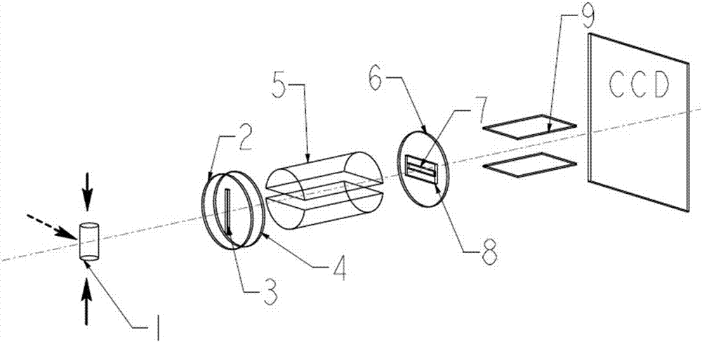
[0023] figure 1 It is a structural schematic diagram of a time-sequence diagnostic system for joint targeting of nanosecond and picosecond laser beams according to the present invention, wherein the solid line arrows represent nanosecond laser beams, and the dotted line arrows represent picosecond laser beams. exist figure 1 Among them, the timing diagnostic system for combined targeting of nanosecond and picosecond laser beams of the present invention includes an imaging slit plate 2, a filter 4, a hard X-ray shield 5, a photocathode slit plate 6, a photocathode 8 and Streak Camera9.

[0024] The imaging slit plate 2 is provided with a vertical slit 3 , and a filter 4 is pasted on the rear end surface of the imaging slit plate 2 .

[0025] The hard X-ray shielding body 5 is composed of two parallel semi-cylinders, and a gap is provided between the two semi-cylindrical planes to limit the area where the high-energy X-rays generated by picosecond targeting irradiate the photo...

Embodiment 2

[0037] The structure of this embodiment is the same as that of Embodiment 1, except that the material of the slit plate is Cu, and the thickness is 40 μm.

Embodiment 3

[0039] The structure of this embodiment is the same as that of Embodiment 1, except that the material of the slit plate 1 is Mo, and the thickness is 25 μm.


PUM


Abstract

The invention discloses a sequential diagnosis system used for nanosecond and picosecond laser beam combined targeting, and is used for sequential precision diagnosis in combined targeting by using nanosecond laser beams and picosecond laser beams simultaneously in a laser plasma experiment. The sequential diagnosis system comprises an imaging slit plate, a hard X-ray shielding body, a photocathode slit plate, a photocathode and a streak camera which are arranged in turn along a horizontal direction. In the experiment, soft X-rays generated by nanosecond laser beam targeting are imaged through the slit plate and then irradiated to the partial area of the photocathode; and hard X-rays generated by picosecond laser beam targeting directly penetrate through the slit plate (without imaging) and then irradiate all the area of the photocathode. Two types of X-rays of which the original light source positions are overlapped can be spatially separated on the images recorded by the streak camera so that diagnosis of the sequential relationship between the nanosecond laser beams and the picosecond laser beams can be realized. The sequential diagnosis system has ten picosecond level time discrimination and also has certain soft X-ray spatial discrimination so as to have wide application prospect.

Description

technical field [0001] The invention belongs to the field of laser fusion research and the field of X-ray detection, and in particular relates to a timing diagnosis system for joint targeting of nanosecond and picosecond laser beams. Background technique [0002] With the rapid development of ultra-short pulse laser technology, more and more laser beams with multiple power densities are used for joint targeting in laser experimental research: such as nanosecond laser beams and picosecond laser beams for joint target physical research . A typical application is in the research of fast ignition physics. It is necessary to use the nanosecond laser beam to compress the CD target pellet at the same time, and at the same time use the picosecond laser beam to generate the superthermal electron beam to heat the compressed plasma or generate X-rays. Density diagnosis. These experimental studies urgently need to ensure that the picosecond laser beam is injected into the target point...

Claims


Application Information

Patent Timeline
Patent Type & Authority Applications(China)
IPC IPC(8): G01T1/29
CPCG01T1/2921Y02E30/10
Inventor 张锋单连强李晋卢峰
Owner LASER FUSION RES CENT CHINA ACAD OF ENG PHYSICS
Why Eureka
Try Eureka