Imaging method and device of synthetic aperture radar (SAR)
A technology of synthetic aperture radar and imaging method, which is applied in the field of radar and can solve the problems such as the inability to realize the TOPS mode and the lack of repeated observation.
- Summary
- Abstract
- Description
- Claims
- Application Information
AI Technical Summary
Problems solved by technology
Method used
Image

Examples
Embodiment 1
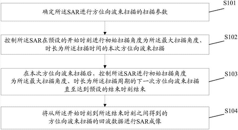
[0028] An embodiment of the present invention provides a synthetic aperture radar imaging method, which is applied to a synthetic aperture radar imaging device, figure 1 It is a schematic diagram of the implementation flow of a synthetic aperture radar imaging method according to an embodiment of the present invention, as figure 1 As shown, the method includes the following steps:
[0029] Step S101, determining the scanning parameters for the SAR to perform azimuth beam scanning;
[0030] Here, the scanning parameters at least include: a maximum scanning angle and a scanning period.
[0031] The step S101 further includes:
[0032] Step S101a, determining initial scanning parameters for the SAR to perform azimuth beam scanning;
[0033] Step S101b, acquiring the antenna step angle of the SAR;
[0034] Here, the antenna step angle is set by the staff according to actual needs.
[0035] Step S101c, according to the initial scanning parameters and the antenna step angle, de...
Embodiment 2
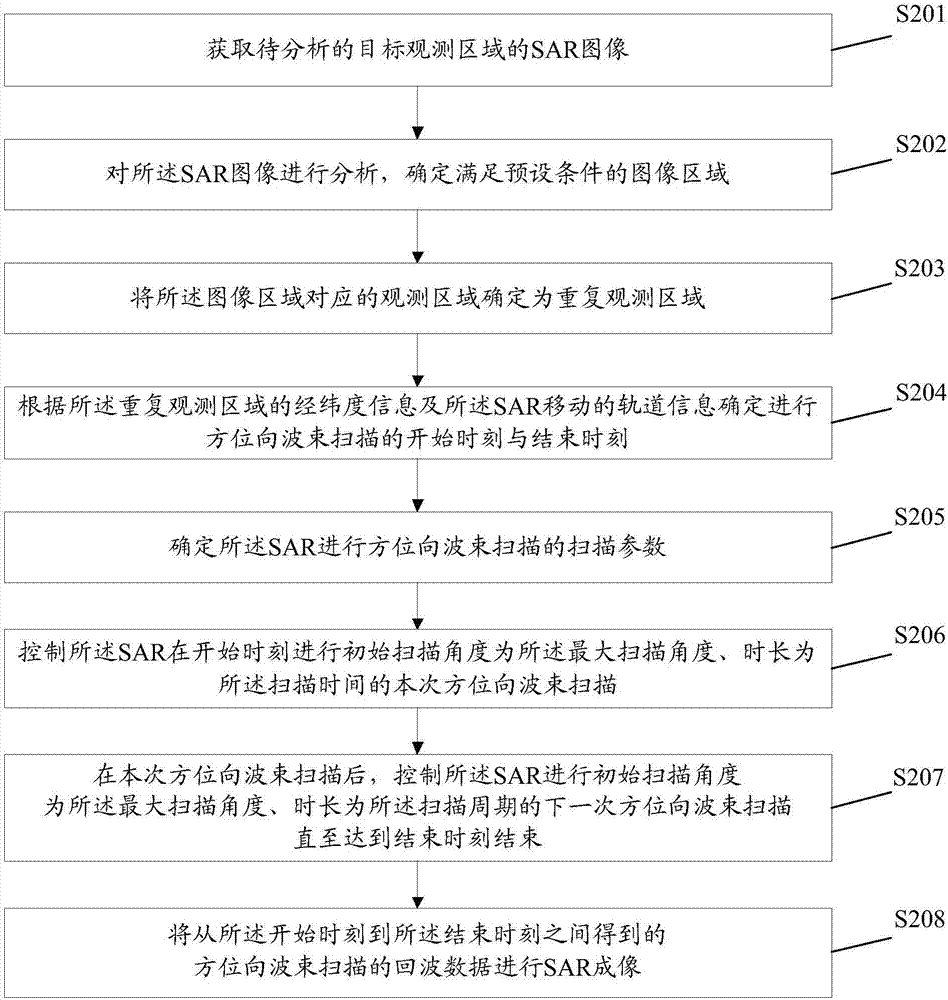
[0046] Based on the foregoing embodiments, an embodiment of the present invention further provides a synthetic aperture radar imaging method, which is applied to a synthetic aperture radar imaging device, and the synthetic aperture radar imaging device may be a processor in an actual implementation process. figure 2 It is a schematic diagram of the implementation process of the second synthetic aperture radar imaging method of the present invention, as figure 2 As shown, the method includes the following steps:
[0047] Step S201, acquiring the SAR image of the target observation area to be analyzed;
[0048] Here, the SAR image may be obtained before the synthetic aperture radar used in the embodiment of the present invention, or may be obtained by using other synthetic aperture radars.
[0049] Step S202, analyzing the SAR image to determine an image area that meets preset conditions;
[0050] Here, the preset conditions may be set according to observation requirements i...
Embodiment 3
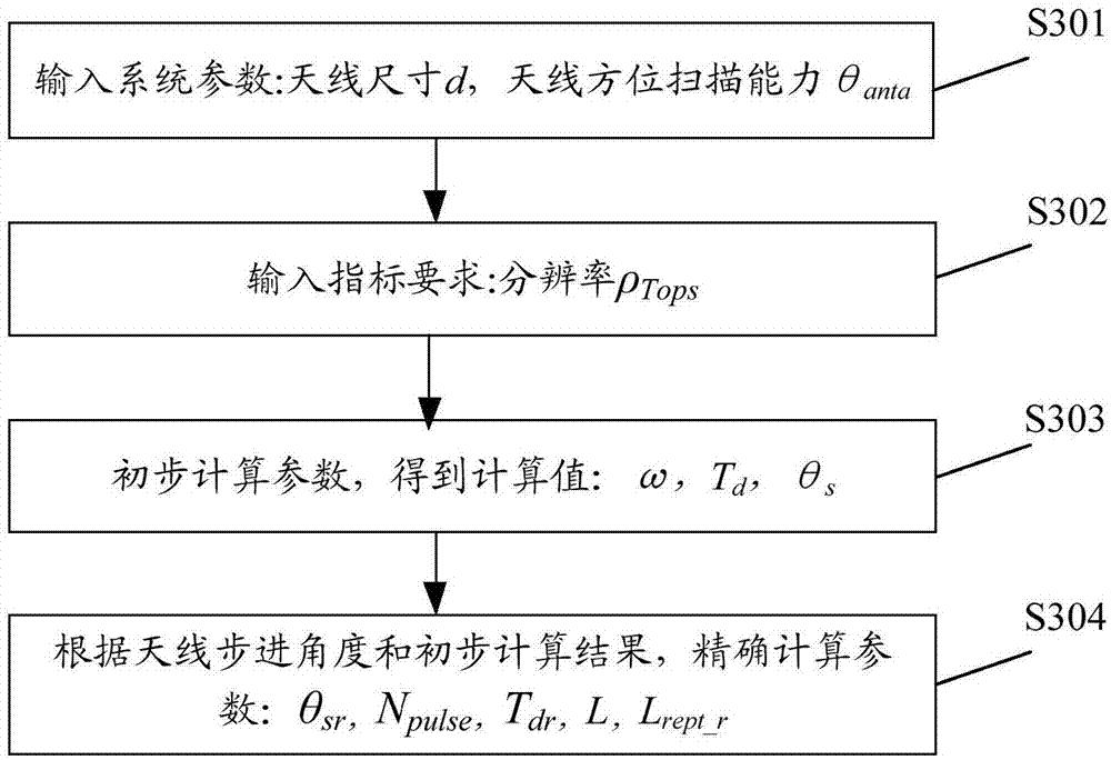
[0108] The embodiment of the present invention firstly provides a method for realizing repeated observation of the ground by synthetic aperture radar. In this method, only azimuth scanning is required, and by controlling the beam azimuth scanning speed, the same Repeated observations of the region. image 3 It is a schematic diagram of the implementation process of the implementation method of the third synthetic aperture radar to repeat the observation of the ground in the embodiment of the present invention, as image 3 As shown, the method includes the following steps:
[0109] Step S301, determine the input system parameters;
[0110] Here, the system parameters at least include: antenna size and antenna azimuth scanning capability (that is, the actual maximum scanning angle of the antenna azimuth).
[0111] Step S302, determining the input index requirement, that is, the azimuth resolution;
[0112] Step S303, according to the system parameters and the required resolut...
PUM
 Abstract
Description
Claims
Application Information
 - R&D
- Intellectual Property
- Life Sciences
- Materials
- Tech Scout
- Unparalleled Data Quality
- Higher Quality Content
- 60% Fewer Hallucinations
Browse by: Latest US Patents, China's latest patents, Technical Efficacy Thesaurus, Application Domain, Technology Topic, Popular Technical Reports.
© 2025 PatSnap. All rights reserved.Legal|Privacy policy|Modern Slavery Act Transparency Statement|Sitemap|About US| Contact US: help@patsnap.com