
Gynaecological and obstetrical forceps

A kind of midwifery forceps, obstetrics and gynecology technology, applied in the field of medical equipment, can solve the problems of head deformation, full fit of the baby's head, inconvenient use, etc., and achieve the effect of convenient operation and simple structure

Inactive Publication Date: 2017-06-30
彭辉
View PDF2 Cites 1 Cited by
  • Summary
  • Abstract
  • Description
  • Claims
  • Application Information

AI Technical Summary

Problems solved by technology

When the fetal head suction device is used for midwifery, since the suction cup is set on the baby's head and has a certain negative pressure, it is easy to cause fetal intracranial hemorrhage or head deformation during midwifery, which seriously affects the baby's health. Safety, when midwifery is carried out by midwifery forceps, since the existing midwifery forceps are generally placed on the lower edge of the auricles on both sides of the baby's head when the existing midwifery forceps are used, the baby's head is buckled by the forceps handle to hold the baby This is not only inconvenient to use, but also because of the difference in the size of the fetal head, relying on the experience of medical staff to hold the midwifery forceps is likely to cause injury to the mother and baby, and it is difficult for the baby to pass through when encountering resistance from the puerpera's basin. The midwifery forceps delivered the baby smoothly; this not only brought difficulties to the medical staff; it also aggravated the pain of the puerpera. Insufficient fit

Method used


Image

  • Gynaecological and obstetrical forceps

Examples


Embodiment Construction

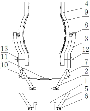
[0014] The obstetrics and gynecology forceps are composed of a handle 1, a pulling handle 2, a forceps arm 3, a clamping arm 4 and a supporting arm 5. The two ends of the handle 1 are movably installed with a support arm 5 through the pin shaft 6 in a symmetrical shape; One end of the rod 7 is connected with the support arm 5 through the pin shaft 6, and the other end of the extrusion rod 7 is connected with the pincer arm 3 through the pin shaft 6.

[0015] The inner side of the upper end of the pincer arm 3 is movably installed with the clamping arm 4 through the pin 8 and the connecting ear, and the pulling handle 2 is movably installed through the pin shaft 6 between the lower ends of the plier arm. The inner side of the clamping arm 4 is provided with a non-slip pad 9 to increase the friction between the clamping arm 4 and the baby's head during use to prevent slipping.

[0016] Screw rods 10 are arranged on the inner side of the ends of the support arms 5 , and the scre...


PUM


Abstract

The invention relates to a s, which belongs to the technical field of medical apparatus and instruments. The pair of gynaecological and obstetrical forceps is formed by a handle, a traction handle, tong arms, clamping arms and supporting arms, wherein the supporting arms are movably arranged on two ends of the handle; the tong arms are arranged on the end heads of the supporting arms; an extrusion rod is arranged between each tong arm and the corresponding supporting arm; one end of each extrusion rod is connected with the corresponding supporting arm; the other end of each extrusion rod is connected with the corresponding tong arm; the clamping arms are arranged on the inner sides of the end heads of certain ends of the tong arms; the traction handle is arranged between the other end heads of the tong arms. The pair of gynaecological and obstetrical forceps is simple in structure and convenient to operate and use; during a use process, the left clamping arm and the right clamping arm can rotate within a certain angle under the action of a dowel, so as to fully coincide to the head part of an infant, so that a pregnant woman can give birth to the infant successfully. The pair of gynaecological and obstetrical forceps solves the problem that an existing pair of obstetrical forceps cannot fully coincide to the head part of the infant during a use process due to an integrated structure, and is particularly suitable for obstetricians to assist the pregnant woman to give birth to the infant.

Description

technical field [0001] The invention relates to obstetrics and gynecology midwifery forceps, belonging to the technical field of medical instruments. Background technique [0002] When obstetricians and gynecologists perform natural childbirth for mothers, they need doctors to assist in delivering the baby. When the baby's head is exposed, in order to prevent the baby from suffocating, the doctor usually supports the baby's head with both hands and cooperates with the mother to drag the baby. Out of the womb, in order to achieve the purpose of mother and child safety. Under normal circumstances, there are also midwifery devices to help the mother deliver; the most commonly used midwifery devices in the obstetrics and gynecology department of the hospital are midwifery forceps and fetal head aspirators. output. When the fetal head suction device is used for midwifery, since the suction cup is set on the baby's head and has a certain negative pressure, it is easy to cause fe...

Claims


Application Information

Patent Timeline
Patent Type & Authority Applications(China)
IPC IPC(8): A61B17/44
CPCA61B17/44
Inventor 彭辉
Owner 彭辉
Learn More