
Computational hologram based on liquid crystal material and its manufacturing method

A technology for computational holograms and liquid crystal materials, applied in the field of computational holograms, can solve the problems of complex production, long cycle and expensive, and achieve the effect of short processing cycle and simple production process

Active Publication Date: 2019-05-10
BEIJING INSTITUTE OF TECHNOLOGYGY
View PDF3 Cites 0 Cited by
  • Summary
  • Abstract
  • Description
  • Claims
  • Application Information

AI Technical Summary

Problems solved by technology

[0009] Aiming at the problem of complex, expensive and long-term production of traditional high-precision computational holograms based on photolithography technology in the existing high-precision laser interferometry to detect surface shape errors of optical elements, the invention discloses a computational hologram based on liquid crystal materials. Figure and its production method, the technical problem to be solved is to provide a high-precision, cheap calculation hologram and its production method, the production method has the advantages of short production cycle and simple process

Method used


Image

  • Computational hologram based on liquid crystal material and its manufacturing method
  • Computational hologram based on liquid crystal material and its manufacturing method
  • Computational hologram based on liquid crystal material and its manufacturing method

Examples


Embodiment 1

[0055] The liquid crystal material-based computational hologram disclosed in this embodiment is suitable for the laser interferometry detection of surface error of high-precision optical elements, especially for complex aspheric surface error detection of laser interferometry.

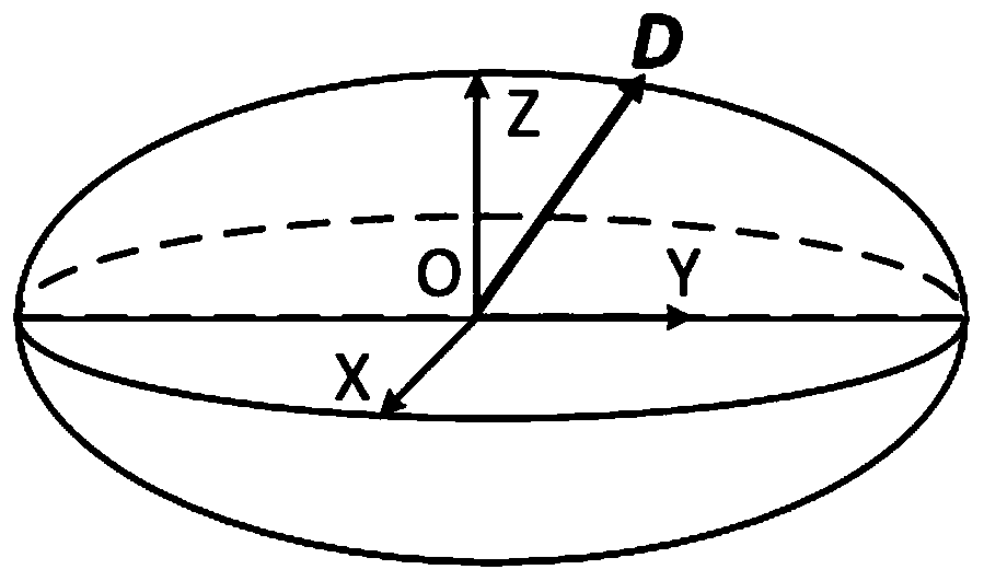
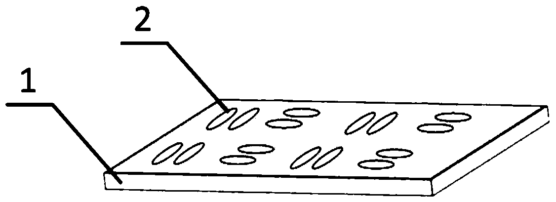
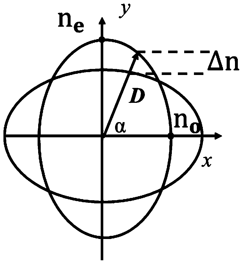
[0056] A liquid crystal material-based computational hologram disclosed in this embodiment includes a glass substrate 1 with uniform transmittance and a liquid crystal material 2 coated on the substrate 1 . The direction of the liquid crystal molecules in the adjacent stripes of the liquid crystal material 2 is controlled by the optical control orientation technology. The stripes will have different refractive indices for the incident light with the same known incident direction and polarization direction. Material 2 will generate a phase difference, that is, form a computational hologram with a fixed phase difference that compensates for the incident laser light.

[0057] The glass substrate with unif...

Embodiment 2

[0093] The aspheric surface to be measured and the measuring optical path in this embodiment are the same as those in Embodiment 1, the only difference is that the thickness of the selected liquid crystal material 2 is different. In the first embodiment, the thickness of the liquid crystal material 2 is selected as 2 microns, and in this embodiment, the thickness of the liquid crystal is selected as 6 microns.

[0094] The fabrication method is the same as above, after four steps of calculation and design, the final computational hologram is shown in Figure 8(a) and Figure 8(b). 8(a) is the pattern distribution of the liquid crystal computational hologram, and Fig. 8(b) is the enlargement of the central area. Compared with the design results in Example 1, it can be seen that in this example, because the thickness of the liquid crystal material 2 is set differently, the final stripe distribution is obviously sparse, which will greatly reduce the difficulty and processing cost o...


PUM


Abstract

The invention discloses a computer generated hologram based on liquid crystal materials and a manufacturing method thereof and belongs to the photoelectric detection field. According to the computer generated hologram based on the liquid crystal materials, a uniform transmittance substrate and the liquid crystal materials coated on the substrate are comprised; liquid crystal molecules of adjacent stripes of the liquid crystal materials are controlled through the light control orientation technology for being in different directions, and incident laser passes through the liquid crystal materials with fixed thickness and different refractive indexes and then generates fixed phase difference; the substrate and the liquid crystal materials form the computer generated hologram having a function of compensating the fixed phase difference of the incident laser; the phase difference is realized through adjusting thickness of the liquid crystal materials or replacing the liquid crystal materials to change a liquid crystal material refractive index. The invention further discloses a manufacturing method of the computer generated hologram. The computer generated hologram has high precision and low cost, the manufacturing method has a short manufacturing period and simple technology, and the computer generated hologram is suitable for detecting an optical element surface shape error through high precision laser interferometry and is suitable for detecting complex aspheric surface shapes through the laser interferometry.

Description

technical field [0001] The invention relates to a calculation hologram used for measuring the surface shape of an optical element by laser interferometry, belonging to the field of photoelectric detection. Background technique [0002] Compared with spherical surfaces, aspheric surfaces can greatly reduce the size and quality of the optical system, improve the imaging quality of the system, and even reach the diffraction limit because they have more degrees of freedom in surface shape. They are more and more used in modern optical systems. more extensive. However, because of its high-degree-of-freedom surface shape, high-precision aspheric surface shape detection has always been a major problem in the field of optical detection. [0003] At present, the commonly used aspheric surface shape detection methods are mainly divided into two types: contact and non-contact measurement methods. The contact method uses a special probe to perform contact point-to-point measurement on...

Claims


Application Information

Patent Timeline
Patent Type & Authority Patents(China)
IPC IPC(8): G01B11/06G03H1/08
CPCG01B11/0675G03H1/08
Inventor 王劭溥胡摇郝群
Owner BEIJING INSTITUTE OF TECHNOLOGYGY
Learn More