
An integrated CNC engraving machine equipment

A CNC engraving machine, an all-in-one technology, applied in the direction of engraving, decorative arts, processing models, etc., can solve the problems of increased input cost, low work efficiency, and difficulty in achieving cleaning effects, and achieves the improvement of processing speed and reduction of operation steps. Effect

Active Publication Date: 2017-12-01
日照市中腾机械有限责任公司
View PDF6 Cites 0 Cited by
  • Summary
  • Abstract
  • Description
  • Claims
  • Application Information

AI Technical Summary

Problems solved by technology

[0002] LED lamps are often used in workpiece engraving. Since there will be more dust on the surface of the engraved workpiece, it needs to be cleaned in order to maintain cleanliness. The existing cleaning of the engraved workpiece is generally done by manual operation. The working efficiency is extremely low and it is difficult to achieve the ideal cleaning effect, which has great disadvantages. At the same time, the existing LED lights have a single function and do not have the cleaning function. For the cleaning of the workpiece, it is necessary to purchase another cleaning device, which increases the investment cost. , causing inconvenience to users

Method used


Image

  • An integrated CNC engraving machine equipment
  • An integrated CNC engraving machine equipment
  • An integrated CNC engraving machine equipment

Examples


Embodiment Construction

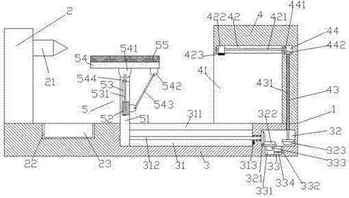
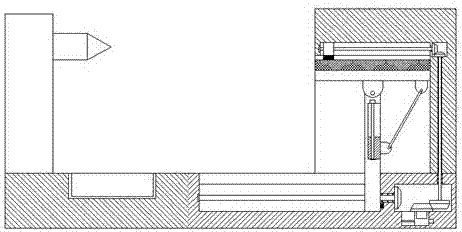
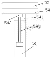
[0018] Such as figure 1 and image 3 As shown, a kind of integrated numerical control engraving machine equipment of the present invention comprises frame 3, and the upper left side of described frame 3 is provided with the numerical control engraving machine 2 that can slide according to track on described frame 3, and described numerical control A steerable engraving drill 21 is provided on the upper right side of the engraving machine 2, and a dust removal part 4 is provided on the upper right side of the stand 3, and on the stand 3 between the CNC engraving machine 2 and the dust removal part 4 A workpiece part 5 is provided, and a first sliding groove 31 is provided inside the right side of the frame 3 between the workpiece part 5 and the dust removal part 4, and a first slide groove 31 is provided on the top of the first slide groove 31. A connecting groove 311 extending from a sliding groove 31, a first drive chamber 32 is provided in the frame 3 on the right side of t...


PUM


Abstract

The invention discloses an integrated numerical control carving machine device which comprises a frame seat. A numerical control carving machine capable of sliding on the frame seat according to the track is arranged above the left side of the frame seat. A carving drill bit capable of steering is arranged above the right side of the numerical control carving machine. A dust removing part is arranged above the right side of the frame seat. A workpiece part is arranged at the position, between the numerical control carving machine and the dust removing part, on the frame seat. A first sliding groove is formed in the position, between the workpiece part and the dust removing part, in the right side of the frame seat. A communication groove extending along the first sliding groove is formed in the top of the first sliding groove. A first drive cavity is formed in the position, on the right side of the first sliding groove, in the frame seat. A first screw rod extending towards the left side and the right side is arranged in the first sliding groove. An extending section of the right side of the first spiral rod penetrates the inner wall of the frame seat and is connected with the inner wall of the frame seat in a rotation fit manner. The tail end of the right side of the first spiral rod extends in the first drive cavity and is provided with a first gear. A second sliding groove is formed in the bottom of the first drive cavity, a second spiral rod is arranged in the second sliding groove, and the tail end of the right side of the second spiral rod is connected with a first driving machine.

Description

technical field [0001] The invention relates to the technical field of numerical control engraving machines, in particular to an integrated numerical control engraving machine equipment. Background technique [0002] LED lamps are often used in workpiece engraving. Since there will be more dust on the surface of the engraved workpiece, it needs to be cleaned in order to maintain cleanliness. The existing cleaning of the engraved workpiece is generally done by manual operation. The working efficiency is extremely low and it is difficult to achieve the ideal cleaning effect, which has great disadvantages. At the same time, the existing LED lights have a single function and do not have the cleaning function. For the cleaning of the workpiece, it is necessary to purchase another cleaning device, which increases the investment cost. , causing inconvenience to users. Contents of the invention [0003] The technical problem to be solved by the present invention is to provide an ...

Claims


Application Information

Patent Timeline
Patent Type & Authority Patents(China)
IPC IPC(8): B44B1/06B44B3/06
CPCB44B1/06B44B3/06
Inventor 李军
Owner 日照市中腾机械有限责任公司
Learn More