Small size digital controlled lathe spindle transmission mechanism

A technology of CNC lathe and spindle transmission, which is applied to driving devices, large fixed members, metal processing machinery parts, etc., can solve the problems of incomplete transmission system structure, inconvenient access to the spindle rotation angle, low axial load capacity, etc. Reliable, convenient rotation angle displacement, the effect of large axial load

Pending Publication Date: 2017-06-27
ANHUI CHIZHOU WEISS ELECTROMECHANICAL
View PDF0 Cites 2 Cited by
  • Summary
  • Abstract
  • Description
  • Claims
  • Application Information

AI Technical Summary

Problems solved by technology

[0002] With the popularization of family cars, many families have begun to pay attention to the maintenance of cars after a period of use. The expensive 4S charges make many families discouraged when cars break down. Therefore, more and more families hope to solve the problems of family cars by themselves. The demand for small lathes is increasing due to small faults during use. In order to simplify the operation difficulty of the machine tools, the ordinary small lathes are replaced by small CNC lathes. The traditional small CNC lathes have small adaptability and the structure of the transmission system. Some are not perfect, and it takes a lot of auxiliary time to adjust the machine tool, and the efficiency is low. Some machine tools have low axial load bearing capacity, poor transmission accuracy, and the spindle angle cannot be easily obtained.

Method used


Image

  • Small size digital controlled lathe spindle transmission mechanism
  • Small size digital controlled lathe spindle transmission mechanism

Examples


Embodiment Construction

[0015] In order to make the technical means, creative features, goals and effects achieved by the present invention easy to understand, the present invention will be further described below in conjunction with specific illustrations.

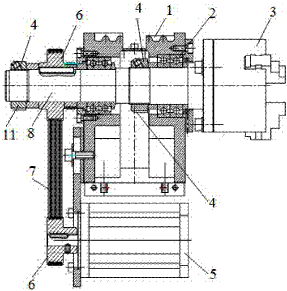
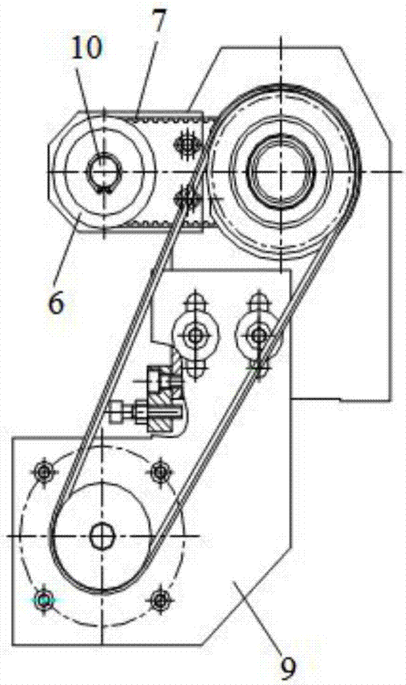
[0016] A small CNC lathe spindle transmission mechanism, including a spindle box 1, a bearing 2, a three-jaw chuck 3, a nut 4, a servo motor 5, a pulley 6, a belt 7, a spindle 8, a motor bracket 9, an encoder 10, and a shaft sleeve 11 , the servo motor 5 is arranged under the main shaft box 1, the pulley 6 on the left side of the servo motor 5 is connected to the pulley 6 sleeved on the left end of the main shaft 8 through a belt 7, the main shaft 8 and the pulley 6 are driven by a flat key, and the left end of the main shaft 8 The belt pulley 6 is fixed by a shaft sleeve 11, the shaft sleeve 11 and the main shaft 8 are fixed by a nut 4, the right end of the main shaft 8 and the hole of the main shaft box 1 are supported by a bearing 2, and the r...


PUM


Abstract

The invention discloses a small CNC lathe spindle transmission mechanism, which belongs to the technical field of mechanical device design, including a spindle box, a bearing, a three-jaw chuck, a nut, a servo motor, a pulley, a belt, a spindle, a motor bracket, an encoder, The shaft sleeve, the servo motor is set under the main shaft box, the pulley on the left side of the servo motor is connected to the pulley on the left end of the main shaft through a belt, the main shaft and the pulley are driven by a flat key, and the pulley on the left end of the main shaft is fixed by a shaft sleeve. The sleeve and the main shaft are fixed by nuts, the right end of the main shaft and the hole of the main shaft box are supported by bearings, the right end of the main shaft is provided with a three-jaw chuck, and the servo motor is fixed in the motor bracket. The mechanism can bear a large axial load, the transmission is stable, the price is cheap, the shaft sleeve and the main shaft are fixed conveniently and reliably, the transmission accuracy is good, and the rotation angle displacement of the pulley is convenient.

Description

technical field [0001] The invention relates to the technical field of mechanical device design, in particular to a small numerically controlled lathe spindle transmission mechanism. Background technique [0002] With the popularization of family cars, many families have begun to pay attention to the maintenance of cars after a period of use. The expensive 4S charges make many families discouraged when cars break down. Therefore, more and more families hope to solve the problems of family cars by themselves. The demand for small lathes is increasing due to small faults during use. In order to simplify the operation difficulty of the machine tools, the ordinary small lathes are replaced by small CNC lathes. The traditional small CNC lathes have small adaptability and the structure of the transmission system. Some are not perfect, and it takes a lot of auxiliary time to adjust the machine tool, and the efficiency is low. Some machine tools have low axial load capacity, poor tr...

Claims


Application Information

Patent Timeline
Patent Type & Authority Applications(China)
IPC IPC(8): B23B19/02B23Q5/10
CPCB23Q1/70B23Q5/10
Inventor 陈华生胡国友
Owner ANHUI CHIZHOU WEISS ELECTROMECHANICAL
Why Eureka
Try Eureka