
Brushless Direct Current vibration motor

A vibrating motor and brushless technology, applied in the direction of electric components, electromechanical devices, electrical components, etc., can solve the problems of enlarging the area of ​​the alveolar metal plate, the motor cannot be driven, and the non-start point, etc., to reduce friction noise and improve stop Speed, the effect of eliminating residual vibration

Active Publication Date: 2017-06-23
威海硕科微电机有限公司
View PDF5 Cites 0 Cited by
  • Summary
  • Abstract
  • Description
  • Claims
  • Application Information

AI Technical Summary

Problems solved by technology

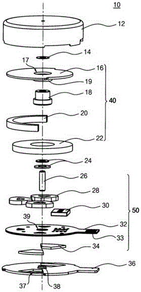
[0013] First, insert the alveolar metal plate (34) into the through hole of the lower casing (36), so the alveolar metal plate (34) will break away from the lower casing (36) when an external impact occurs
A neutral zone (neutral zone) is formed between the N pole and the S pole in the magnet (22). If the built-in Hall sensor of the driver IC is just in the neutral zone, there will be a non-start point, so that the motor cannot be driven.
As a component of the stator, the role of the cogging metal sheet is to make the N pole and S pole of the rotor magnet (22) always be arranged on the Hall sensor, so as to ensure that the rotor stops at the correct position, thereby preventing the non-start point of the motor, and the cogging metal sheet plate (34) detached from the lower housing (36) will not prevent the occurrence of a non-start point
[0014] Second, the alveolar metal plate (34) is inserted through the lower casing (36), and the supporting force of the lower casing (36) to the alveolar metal plate (34) is weakened, so the alveolar metal plate (34) is enlarged area is limited
In the past, in order to eliminate such noises, noise-preventing slides or spacers (14) were installed, so the work was cumbersome

Method used


Image

  • Brushless Direct Current vibration motor
  • Brushless Direct Current vibration motor
  • Brushless Direct Current vibration motor

Examples


Embodiment Construction

[0064] In order to facilitate the implementation of the present invention, a detailed description will be given below in conjunction with the accompanying drawings.

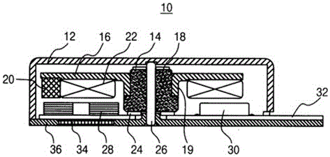
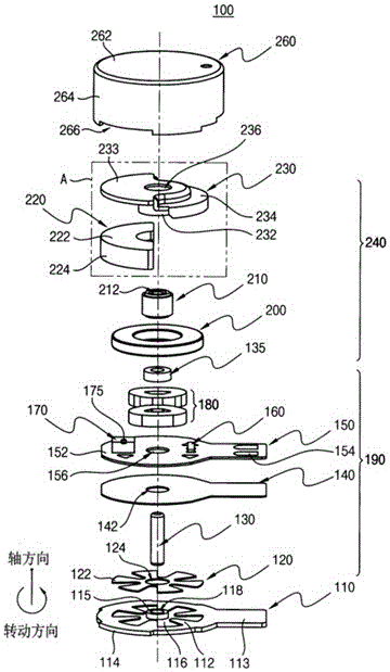
[0065] image 3 is the disassembled state of the components of the BLDC vibration motor (100) in the embodiment of the present invention, Figure 4 It is a cross-sectional view of an assembled BLDC vibration motor (100). The BLDC vibration motor includes a stator (190), a rotor (240), and a casing (110, 260) for accommodating the above two assemblies (190, 240) for protection.

[0066] The upper casing ( 260 ) is sleeve-shaped and has an open bottom. The upper casing ( 260 ) is composed of a circular upper end surface ( 262 ) and side surfaces ( 264 ) bent vertically downward from the edge of the upper end surface ( 262 ).

[0067] The lower casing (110) is composed of a disk portion (112) covering the bottom of the upper casing (260) for sealing and a protruding portion (113) extending horizontally from the edg...


PUM


Abstract

The invention relates to a brushless direct current vibration motor, and the brushless direct current vibration motor has the characteristics that a vibrator on a rotor is fixed between a rack and a permanent magnet so that the upper surface and the lower surface of the vibrator are firmly fixed; the weight of the vibrator can increase the upper end area of the permanent magnet so that the vibrator is beneficial for increasing vibration amount; the upper end and the lower end of a bearing combination part have a clamp for preventing the bearing from getting off; the installation part of a cogged metal sheet of a lower case has a groove shape and isn't pierced, so that the integral supporting force of the lower case is increased; the upper end of the cogged metal sheet installation groove has a boss for preventing the metal sheet from getting off, so that the metal sheet is firmly stuck to the lower case. The cogged metal sheet is connected as a whole, so that the cogged metal sheet can be inserted in the lower case at one time. In this way, the cogged metal sheet area is optimized; the rotor is prevented from getting out when the motor is started; noise of friction with an upper case is prevented; speed for stopping the rotating rotor is improved; residual shaking is eliminated; and an even level of the rotating rotor is guaranteed.

Description

technical field [0001] The invention belongs to the field of vibration motors, and relates to brushless direct current (Brushless Direct Current: BLDC) vibration motors for small electronic instruments such as mobile phones, portable game machines, earphones, and wearable devices. Background technique [0002] In order to facilitate the use of consumers, the smartphone market continues to load various functions necessary for daily life. It is necessary to install hardware in a limited space, and it is necessary to miniaturize the hardware. Vibration motors play the role of transmitting signals on mobile communication terminals such as mobile phones and timers, and are widely used in fields that require vibration, such as: in order to achieve the simulation effect of games, they are used in game consoles; It is used as a reminder function on electronic instruments. The above-mentioned electronic products focus on miniaturization, so the vibration motors used in the above-ment...

Claims


Application Information

Patent Timeline
Patent Type & Authority Applications(China)
IPC IPC(8): H02K1/12H02K1/18H02K1/27H02K11/33H02K11/215H02K5/04H02K7/06H02K29/00
Inventor 李相宜
Owner 威海硕科微电机有限公司
Learn More