Clamp for bone fracture connecting plate bending intensity and equivalent bending rigidity determination and method
A technology of bending strength and bending stiffness, which is applied in the field of bone plate quality inspection, can solve problems such as the inability to measure two sets of deflection values at the same time, the inability to compare differences, and evaluate the quality of bone plates, so as to avoid errors, improve efficiency, and improve general use. sexual effect
- Summary
- Abstract
- Description
- Claims
- Application Information
AI Technical Summary
Problems solved by technology
Method used
Image
Examples
Embodiment 1
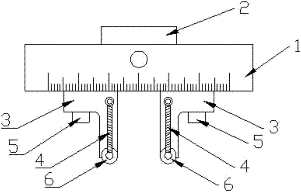
[0066] A jig for measuring the bending strength and stiffness of a bone plate, comprising an upper jig and a lower jig used in conjunction with each other.
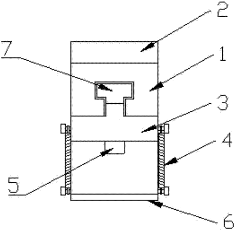
[0067] Such as Figure 1 ~ Figure 3 As shown, the upper fixture includes an upper clamp body 1, and two inner rollers 6 are installed on the lower surface of the upper clamp body 1, and the inner roller shafts 6 are installed on the upper clamp body 1 through the upper adjustment plate 3, and the upper clamp body 1 An upper chute 8 is provided on the lower surface, and the upper adjusting plate 3 can drive the inner roller shaft 6 to slide along the upper chute 8 and realize positioning at any position of the upper chute 8 .
[0068] The upper chute 8 is a T-shaped slot, and the upper chute 8 is provided with an upper mounting block 7 matching it, and the upper mounting block 7 can slide along the upper chute; the upper mounting block 7 is located at the wider part of the top of the T-shaped slot ,Such as figure 2 As s...
Embodiment 2
[0107] The features of this embodiment that are the same as those of Embodiment 1 will not be described in detail. The features of this embodiment that are different from Embodiment 1 are: Figure 8 As shown, the outer roller shaft 13 is columnar, and the surface in contact with the sample is a cylinder of equal diameter, and the shape of the inner roller shaft 6 can be the same as that of the outer roller shaft.
Embodiment 3
[0109] The features of this embodiment that are the same as those of Embodiment 1 will not be described in detail. The features of this embodiment that are different from Embodiment 1 are: Figure 9 As shown, the outer roller shaft 13 is semi-cylindrical with equal diameter, and the surface in contact with the sample is an arc surface, and the shape of the inner roller shaft 6 can be the same as that of the outer roller shaft.
[0110] The shapes of the inner roller shaft 6 and the outer roller shaft 13 of the present invention are not limited to the shapes described in the embodiments, and can also be other shapes. From the aspect of processing technology, the cylindrical shape is a preferred embodiment, but as long as it The contact surface with the sample may be a cylindrical surface of equal diameter, and the arc diameter of the cylindrical surface of equal diameter is preferably 8 mm, 10 mm, 12 mm, and may be other values between 8 mm and 13 mm.
PUM
 Abstract
Description
Claims
Application Information
 - R&D
- Intellectual Property
- Life Sciences
- Materials
- Tech Scout
- Unparalleled Data Quality
- Higher Quality Content
- 60% Fewer Hallucinations
Browse by: Latest US Patents, China's latest patents, Technical Efficacy Thesaurus, Application Domain, Technology Topic, Popular Technical Reports.
© 2025 PatSnap. All rights reserved.Legal|Privacy policy|Modern Slavery Act Transparency Statement|Sitemap|About US| Contact US: help@patsnap.com


