
Strain sensor for weft knitted fabric and knitting method

A technology of strain sensors and knitted fabrics, which is applied in weft knitting, knitting, textiles and papermaking, etc. It can solve problems such as easy detachment and curling of coil courses, small sensor sensitivity coefficient, and sensor application limitations, so as to avoid detachment And curling, overall uniform structure, good extensibility and elastic recovery

Active Publication Date: 2017-06-23
李鹏 +1
View PDF8 Cites 2 Cited by
  • Summary
  • Abstract
  • Description
  • Claims
  • Application Information

AI Technical Summary

Problems solved by technology

The disadvantages of the above-mentioned knitted flexible sensor are: (1) the coil in the connection area has only one yarn, and the density is relatively loose; (2) the coil distribution in the sensing area is rectangular, the sensitivity coefficient of the sensor is small, and the conductive yarn needs to be Lead out from the left and right ends of the sensor; (3) Due to the flat needle structure, the upper and lower edge coil rows of the sensor are easy to fall off and curl
The above deficiencies limit the application of the sensor

Method used


Image

  • Strain sensor for weft knitted fabric and knitting method
  • Strain sensor for weft knitted fabric and knitting method
  • Strain sensor for weft knitted fabric and knitting method

Examples


Embodiment

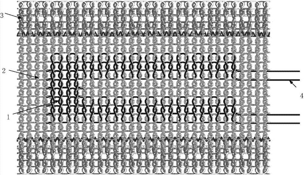
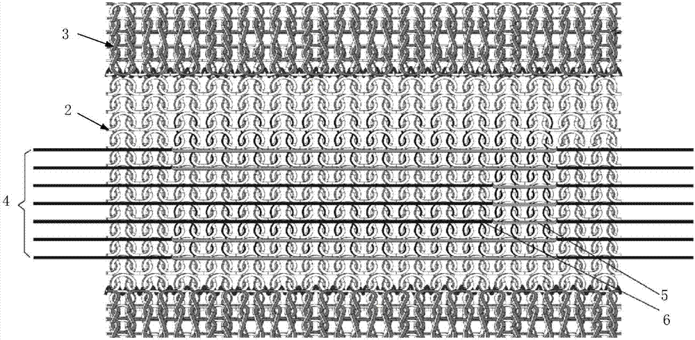
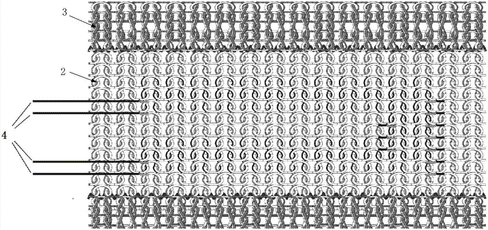
[0044] Such as figure 1 As shown, a weft-knitted fabric strain sensor includes an induction area 1 and a connection area 2, and the induction area 1 is composed of a plain stitch plated coil in which the veil is a conductive yarn and the ground yarn is an elastic yarn. The connection area 2 is located on both sides of the induction area 1, and the connection area 2 is composed of a plain needle plated coil in which the veil is a yarn and the ground yarn is an elastic yarn, and also includes an overlock area 3, and the overlock area 3 Located on the outside of each corresponding connection area 2, the overlock area 3 is composed of flat-stitch plated loops in which the veil is a yarn and the ground yarn is an elastic yarn, wherein the veil is exposed in the induction area 1, the connection area 2 and the lock On the front side of the edge area 3, the ground yarn is exposed on the reverse side of the sensing area 1, the connecting area 2 and the overlock area 3, and the conducti...


PUM


Abstract

The invention relates to a strain sensor for weft knitted fabric and a knitting method. The sensor comprises a sensing area and connecting areas. The sensing area comprises plain plaiting coils using face yarn as the conductive yarn and using ground yarn as the elastic yarn. The connecting areas are located at two sides of the sensing area. The connecting areas comprise plain plaiting coils using face yarn as the yarn and the ground yarn as the elastic yarn. Edge locking areas are located at the outer sides of corresponding connecting areas. The edge locking areas comprise plain plaiting coils using face yarn as the yarn and the ground yarn as the elastic yarn, wherein, the face yarn is exposed at the front sides of the sensing area, connecting areas and edge locking areas, and the ground yarn is exposed at the back sides of the sensing area, connecting areas and edge locking areas. The conductive yarn in the sensing area is in a bending structure. The sensor has a good extendability and elastic recovery, the equivalent resistance in the curved sensing area is larger than a rectangular area indicating the sensor has a high sensitivity coefficient.

Description

technical field [0001] The invention relates to a weft-knitted fabric strain sensor, in particular to a weft-knitted fabric strain sensor for measuring tensile and bending strains and a weaving method thereof. Background technique [0002] Weft-knitted fabrics have good extensibility and elasticity, and the equivalent resistance of the weft-knitted structure sensor woven with conductive yarn changes when it is stretched, making it a resistive strain sensor, conductive yarn and elastic yarn The combination of the sensor shows excellent reproducibility. [0003] The weft-knitted sensor can be directly woven or integrated on other carriers (such as clothing, gloves, socks, wristbands, etc.) to form a wearable strain sensor. Different wearable methods make it possible to monitor physiological signals and movement conditions of the human body, such as breathing, heartbeat, and joint mobility. [0004] In the prior art, Chinese Patent No. 201220565490.6 discloses a knitted flexi...

Claims


Application Information

Patent Timeline
IPC IPC(8): D04B1/16D04B1/18D04B1/10D04B1/06D04B15/32D04B15/34D04B15/82
Inventor 龙海如张珏晶沈为贾杰李鹏潘亮
Owner 李鹏
Learn More