Multi-functional moveable rack used for cargo transport and installation method thereof
A cargo transportation and multi-functional technology, applied in the direction of lifting frame, lifting device, etc., can solve the problems of inconvenient cargo at high places, no lifting device, inconvenient cargo handling and placement, etc., to achieve space saving, convenient operation and convenience The effect of expanding business
- Summary
- Abstract
- Description
- Claims
- Application Information
AI Technical Summary
Problems solved by technology
Method used
Image
Examples
Embodiment 1
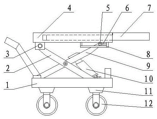
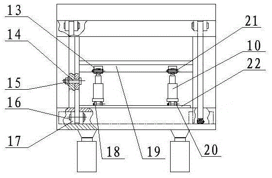
[0028] A multifunctional mobile rack for cargo transportation, which consists of: a shelf body 1, two inner link lower supports 17 are installed below the shelf body, and the inner link lower supports are connected to each other through a connecting shaft A16 One end of the inner connecting rod 9 is connected, the other end of the inner connecting rod is connected to the roller 5, the inner connecting rod is connected to the two outer connecting rods 2 through the connecting shaft B14, and one end of the connecting shaft B is covered with a nut 15. One end of the outer link is connected with the upper support 3 of the outer link, the upper support of the outer link is connected with the panel 4, the panel is connected with the roller bracket 8, the outer link The other end has a groove, a lower roller is installed in the groove, a connecting shaft D is installed in the lower roller, and the connecting shaft D passes through the outer connecting rod.
Embodiment 2
[0030] According to the multifunctional mobile rack for cargo transportation according to embodiment 1, the panel has a sliding groove, an extension plate 7 is installed in the sliding groove, and a fixing block 6 is installed under the panel. The fixed block is connected with the roller bracket.
Embodiment 3
[0032] According to the multifunctional mobile frame for cargo transportation according to embodiment 1, the transverse rib 22 is welded in the groove of the frame device, and two lower cylinder supports 18 are welded on the transverse rib. A cross beam 19 is installed between the connecting rods. Two upper cylinder supports 13 are welded on the cross beam. The upper cylinder support is connected to the upper lug of the cylinder through a connecting shaft C21. The lower cylinder support The connecting shaft E20 is connected with the lower lug of the oil cylinder, and the oil cylinder 10 is installed between the cross rib and the cross beam.
PUM
 Abstract
Description
Claims
Application Information
 - R&D
- Intellectual Property
- Life Sciences
- Materials
- Tech Scout
- Unparalleled Data Quality
- Higher Quality Content
- 60% Fewer Hallucinations
Browse by: Latest US Patents, China's latest patents, Technical Efficacy Thesaurus, Application Domain, Technology Topic, Popular Technical Reports.
© 2025 PatSnap. All rights reserved.Legal|Privacy policy|Modern Slavery Act Transparency Statement|Sitemap|About US| Contact US: help@patsnap.com


