
High-voltage cable pluggable-type intermediate connector for test and cable test device

A technology of high-voltage cables and intermediate joints, applied in the direction of measuring devices, measuring electricity, measuring electrical variables, etc., can solve the problems of judgment interference of test results, single structure of intermediate joints, and no plug-in function, etc. Effect of high current carrying capacity

Pending Publication Date: 2017-06-20
ELECTRIC POWER RES INST OF STATE GRID ZHEJIANG ELECTRIC POWER COMAPNY +1
View PDF6 Cites 6 Cited by
  • Summary
  • Abstract
  • Description
  • Claims
  • Application Information

AI Technical Summary

Problems solved by technology

[0003] At present, there are many high-voltage cable intermediate joint defect simulation tests carried out in China, but the intermediate joint structure used is relatively simple, and can only simulate a single defect, and none of them have the plug-in function. When observing the defect situation, the intermediate joint needs to be destroyed. Irreversible and easy to cause damage to defect parts, which directly interferes with the judgment of test results

Method used


Image

  • High-voltage cable pluggable-type intermediate connector for test and cable test device
  • High-voltage cable pluggable-type intermediate connector for test and cable test device
  • High-voltage cable pluggable-type intermediate connector for test and cable test device

Examples


Embodiment 1

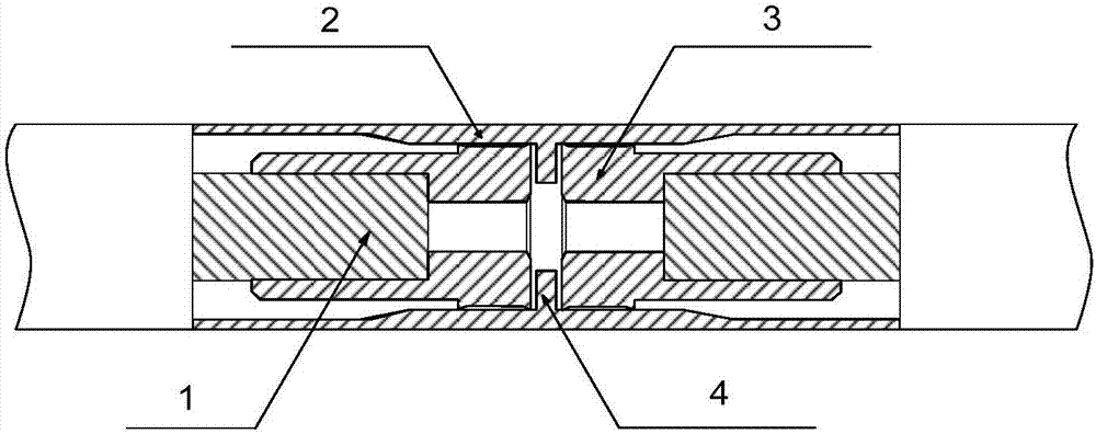
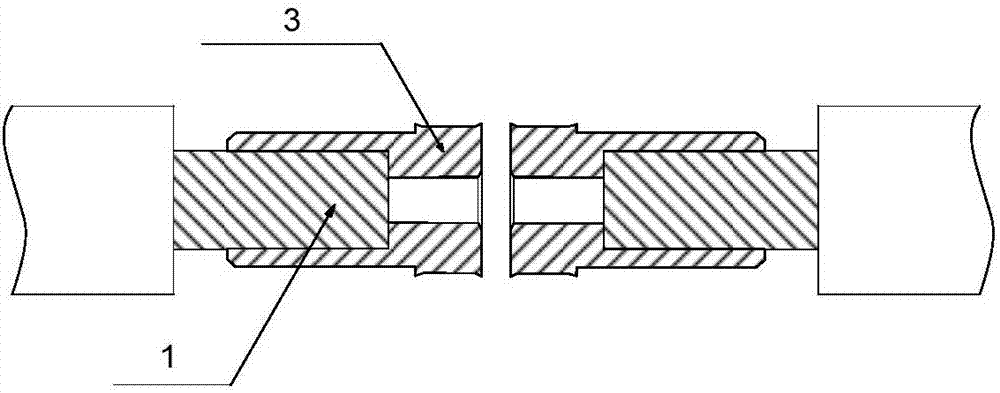
[0024] like Figure 1-2 In the shown high-voltage cable plug-in intermediate connector, the ends of the two cable conductors 1 are covered with a contact 3 . The two contacts 3 are pluggably connected to both ends of the tubular metal shield 2 respectively. A partition 4 for positioning the insertion position of the cable conductor is provided at the middle part of the inner side wall of the metal shielding cover 2 .

[0025] The outer wall of the contact 3 and the inner wall of the metal shield 2 are closely connected by a plurality of bumps, and the plurality of bumps are on the outer wall of the contact 3 . A step that can be positioned and connected to the end of the cable conductor is formed on the inner wall of the contact. The contact 3 is a strap-type contact. The contact is fixedly connected to the cable conductor. The outer end surface of the contact slightly protrudes from the outer surface of the cable conductor. end face.

[0026] The partition 4 is ring-shaped...

Embodiment 2

[0028] like image 3 The shown cable test device includes the high-voltage cable plug-in intermediate joint 8 for the test in the first embodiment, the movable base 5 and two metal platforms 6 placed on the base, and the metal platform 6 can move horizontally relative to the base , the metal platform is provided with fasteners 7 for fixing cables; the test high-voltage cable plug-in intermediate joint 8 is located between two metal platforms.


PUM


Abstract

The invention discloses a high-voltage cable pluggable-type intermediate connector for test and a cable test device. At present, a large number of defect simulation tests are carried out on high-voltage cable intermediate connectors in China; and however, the intermediate connectors are single in structure, and the intermediate connectors need to be destroyed when observing defects, such process is irreversible and may cause damage to the defect part, and judgment of the test result is interfered directly. The high-voltage cable pluggable-type intermediate connector comprises two sections of cable conductors. The tail end of each of the two sections of cable conductors is sleeved by a contact. The two contacts are in pluggable connection with the two ends of a tubular metal shield cover respectively. The high-voltage cable intermediate connector adopts a non-fixed pluggable structure; the band-type contacts can realize tight connection between the conductors and the metal shield cover, thereby ensuring large-current flow capacity; and the pluggable intermediate connector is wholly placed on a mobile base, so that the defect part can be exposed by moving metal platforms so as to observe and adjust defect conditions and facilitate test implementation.

Description

technical field [0001] The invention relates to the field of high-voltage cable intermediate joints, in particular to a high-voltage cable plug-in intermediate joint for testing and a cable testing device. Background technique [0002] With the widespread use of XLPE cables, especially during long-term operation, the cable equipment (including the body and accessories) is affected by factors such as electric fields, thermal effects, mechanical stress, chemical corrosion, and environmental conditions, and the insulation quality gradually deteriorates, which is likely to cause Destruction of the insulation system. As the weakest link of cable line insulation, the high-voltage cable intermediate joint has the highest proportion of operational failures. [0003] At present, there are many high-voltage cable intermediate joint defect simulation tests carried out in China, but the intermediate joint structure used is relatively simple, and can only simulate a single defect, and n...

Claims


Application Information

Patent Timeline
Patent Type & Authority Applications(China)
IPC IPC(8): G01R31/00
CPCG01R31/00
Inventor 蒋愉宽曹俊平王少华刘浩军胡文堂刘黎周象贤李特于淼温典江航骆阗言
Owner ELECTRIC POWER RES INST OF STATE GRID ZHEJIANG ELECTRIC POWER COMAPNY
Learn More