A lifting hinge structure

A technology of hinge structure and hinge piece, which is applied in the direction of hinges with pins, building structures, door/window accessories, etc. It can solve the problems of limited rotation angle of lifting hinges, different lifting hinges, and waterproof failure, so as to reduce the difficulty of processing , to achieve the effect of simple form and simple structure

Active Publication Date: 2018-05-25
FUJIAN XIHE SANITARY WARE TECHNOLOGY CO LTD
View PDF10 Cites 0 Cited by
  • Summary
  • Abstract
  • Description
  • Claims
  • Application Information

AI Technical Summary

Problems solved by technology

[0002] At present, in the field of housing construction, the hinge structure used in the shower room door is generally a common flat hinge, that is, it rotates in the same horizontal direction to realize the opening and closing of the shower room door. The gap between the door and the floor flows out. The common form of waterproofing is to install waterproof rubber strips under the shower door. Because of this, if the shower door is turned in the same horizontal direction, the shower door is in the process of turning. In the process, the waterproof rubber strip is always close to the ground and rotates, which will not only create resistance to the push-pull process of the shower room door, but also easily wear out the waterproof rubber strip installed under the shower room door, resulting in waterproof failure and scratches on the ground; in addition , the existing shower room door also has a structural form that uses a rotating lifting hinge, but the structure of the lifting hinge used to realize the lifting is relatively complicated, and usually due to the influence of the lifting structure, the rotation angle of the lifting hinge is limited. The rotation of a wide range of angles cannot be realized, resulting in the limitation of the lifting hinge due to the different angles between the two shower room doors, and there are also problems such as complicated disassembly and assembly of the hinge

Method used


Image

  • A lifting hinge structure
  • A lifting hinge structure
  • A lifting hinge structure

Examples


Embodiment 1

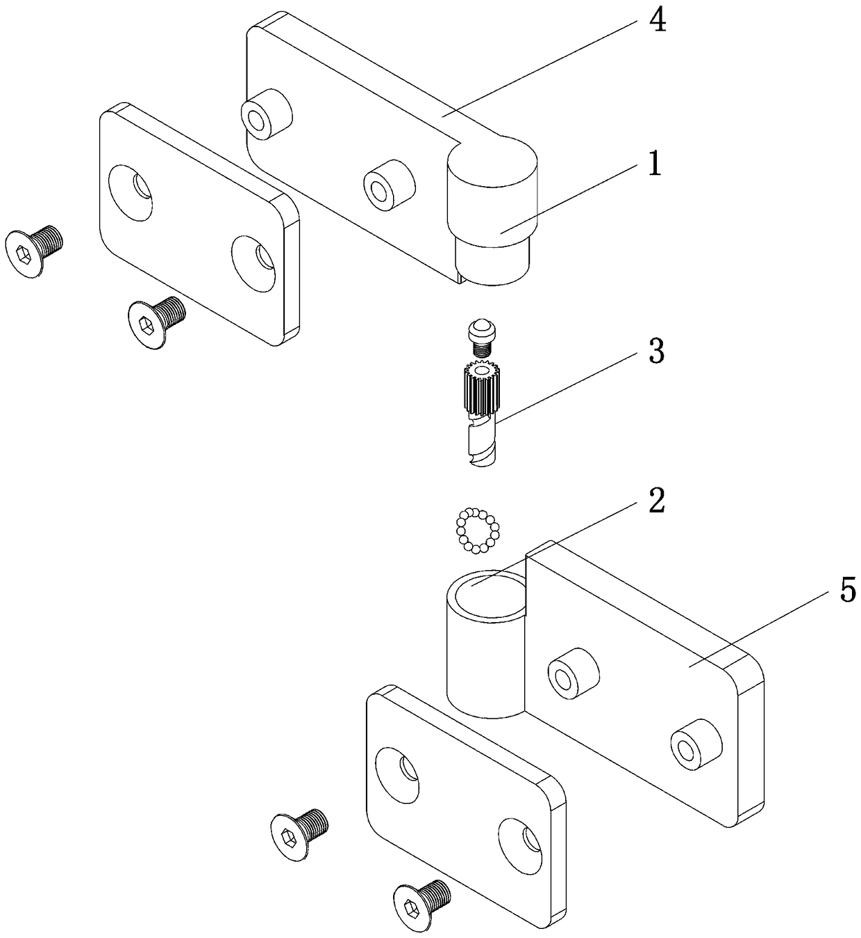
[0047] A first helical groove 331 is set on the outer turning surface of the guide post 33, and a first helical groove 331 matching the first helical groove 331 is set on the turning surface in the small hole 212 of the stepped hole 21 on the lower sleeve 2. The protrusion (not shown in the figure), by screwing the first helical protrusion (not shown in the figure) into the first helical groove 331 , the connection of the guide post 33 in the lower sleeve 2 can be realized.

[0048] Specifically, a helical first curved groove 2122 is set on the inner turning surface of the small hole 212 of the stepped hole 21, and the ball 6 is loaded in the first curved groove 2122, so that the ball 6 exposes the small hole in the stepped hole 21. The spiral protrusion formed on the inner wall surface of 212 constitutes the above-mentioned first spiral protrusion (not shown in the figure).

Embodiment 2

[0050] A second helical groove 2121 is set on the inner turning surface of the small hole 212 of the step hole 21 on the lower sleeve 2, and a second helical groove 2121 adapted to the second helical groove 2121 is set on the outer turning surface of the guide post 33. The protrusion (not shown in the figure), by screwing the second helical protrusion (not shown in the figure) into the second helical groove 2121, the connection of the guide post 33 in the lower sleeve 2 can be realized.

[0051] Specifically, a helical second curved groove 332 is set on the outer turning surface of the guide post 33, and the ball 6 is loaded into the second curved groove 332, so that the ball 6 exposes the spiral shape formed by the outer wall surface of the guide post 33. The protrusion constitutes the above-mentioned second spiral protrusion (not shown in the figure).

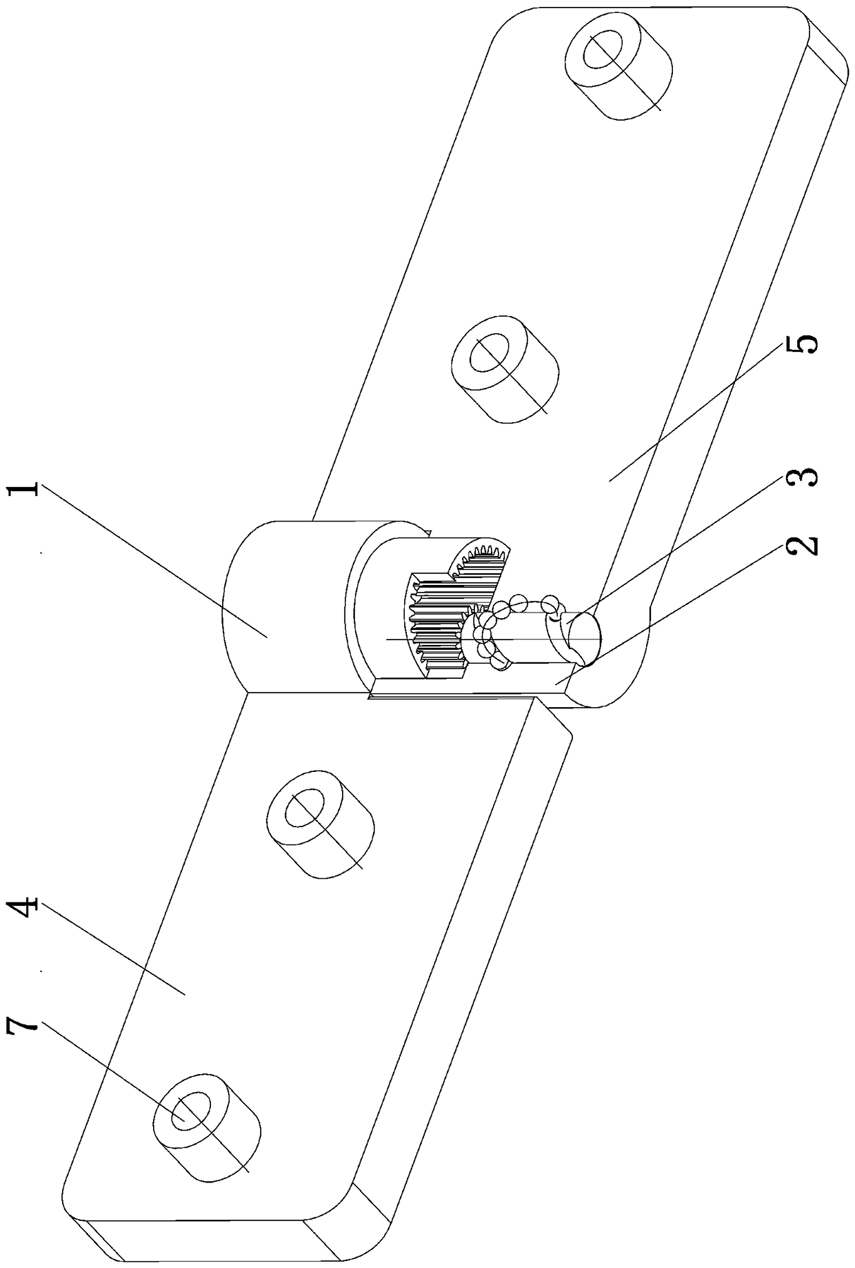
[0052] During the lifting of the hinge structure, the first hinge piece 4 is driven, so that the first hinge piece 4 drives...


PUM


Abstract

The invention discloses a lifting hinge structure. The lifting hinge structure comprises an upper sleeve, a lower sleeve, a connecting rod, a first hinge piece and a second hinge piece. A sealed sleeve bottom is arranged on the upper sleeve. An inner gear is arranged on the inner cylinder wall of the upper sleeve. A stepped hole is formed in the lower sleeve cylinder. A big hole and a small hole in the stepped hole are eccentrically arranged. The connecting rod comprises an abutting portion, a gear portion and a guide column which are fixedly connected into a whole from top to bottom. The guide column of the connecting rod is spirally connected into the small hole of the stepped hole in the lower sleeve and drives the first hinge piece to drive the upper sleeve on the first hinge piece to rotate. Due to the fact that the inner gear on the inner cylinder wall of the upper sleeve and the gear portion on the connecting rod are eccentrically arranged and internally engaged with each other, the gear portion on the connecting rod rotates to drive the connecting rod to spirally rotate up and down in the small hole of the lower sleeve, the abutting portion on the connecting rod abuts against the sleeve bottom of the upper sleeve, and the upper sleeve and the first hinge piece fixedly connected with the upper sleeve ascend and descend in the axial direction. By the adoption of the lifting hinge structure, the large-range angle rotation can be achieved, the structure is simple, and disassembly, assembly and operation are facilitated.

Description

technical field [0001] The invention relates to the technical field of hinge structures, in particular to a rotatable lifting hinge structure. Background technique [0002] At present, in the field of housing construction, the hinge structure used in the shower room door is generally a common flat hinge, that is, it rotates in the same horizontal direction to realize the opening and closing of the shower room door. The gap between the door and the floor flows out. The common form of waterproofing is to install waterproof rubber strips under the shower door. Because of this, if the shower door is turned in the same horizontal direction, the shower door is in the process of turning. In the process, the waterproof rubber strip is always close to the ground and rotates, which will not only create resistance to the push-pull process of the shower room door, but also easily wear out the waterproof rubber strip installed under the shower room door, resulting in waterproof failure a...

Claims


Application Information

Patent Timeline
Patent Type & Authority Patents(China)
IPC IPC(8): E05D3/02E05D7/00E05D5/14E05D5/10
CPCE05D3/02E05D5/10E05D5/14E05D7/0027E05D2007/0036E05Y2900/132
Inventor 林孝发林孝山刘启乔邓小清郑鹏兴
Owner FUJIAN XIHE SANITARY WARE TECHNOLOGY CO LTD
Why Eureka
Try Eureka